
Head-up display device for vehicle

a display device and head-up technology, applied in the direction of static indicating devices, identification means, instruments, etc., can solve the problem of difficult for drivers to early become aware of virtual display images

Inactive Publication Date: 2009-06-04
CALSONIC KANSEI CORP
View PDF6 Cites 57 Cited by
  • Summary
  • Abstract
  • Description
  • Claims
  • Application Information

AI Technical Summary

Benefits of technology

[0008]Therefore, the head-p display device of the invention can help the driver recognize the display image representing the information produced by the head-up display device earlier when the driver looks away from the usual forward visual range to operate the on-vehicle device.

Problems solved by technology

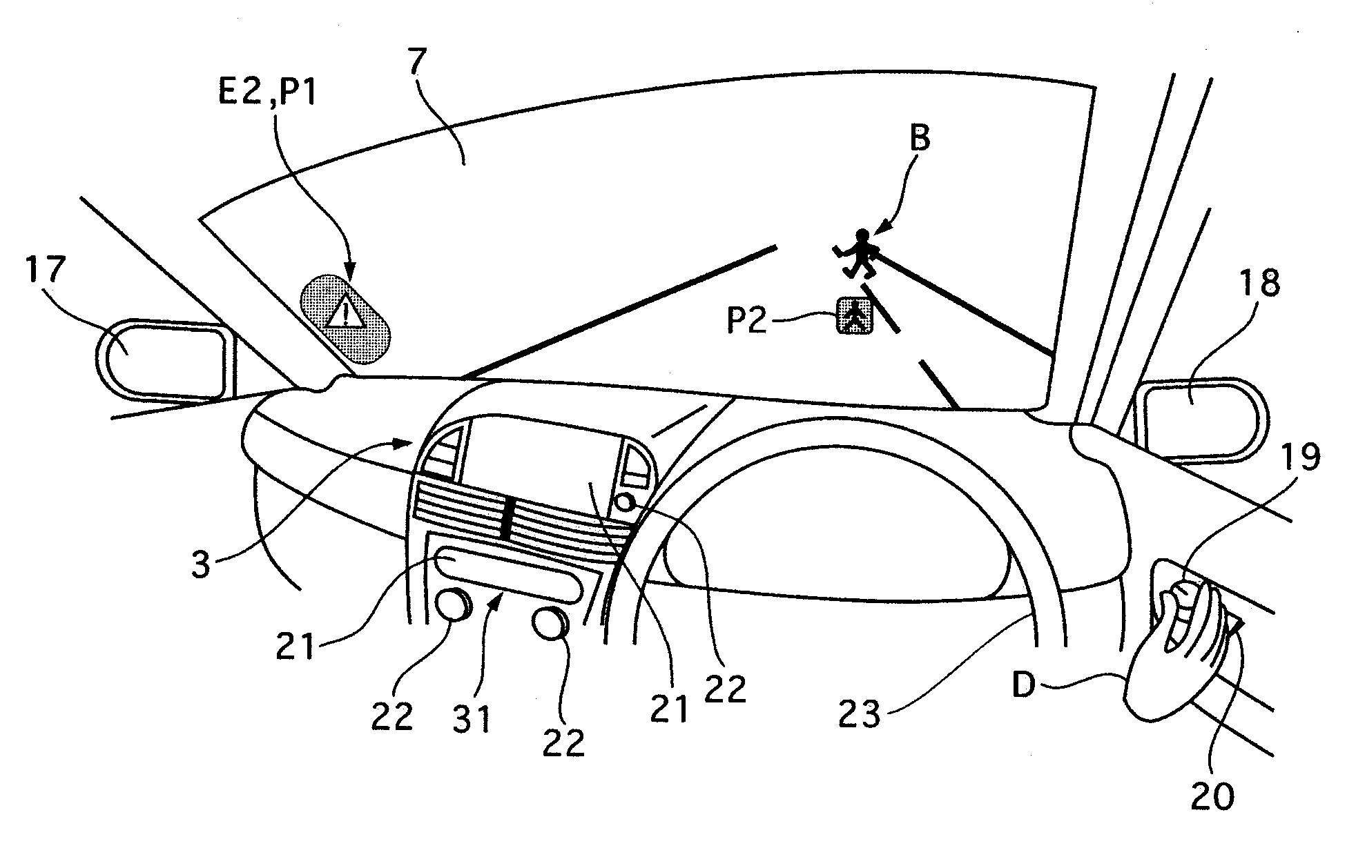
The above known conventional head-up display device, however, encounters a problem in that it is difficult for a driver to early become aware of the virtual display image, especially a warning display image, produced by the head-up display device when the driver looks away considerably from his or her usual forward viewpoint when the driver drives in order to operate a switch of an on-vehicle device, such as a mirror-angle adjustment switch provided on a driver's door, which is distant from the usual forward viewpoint, because positions of the display virtual image and the display area are fixed to be accommodated to the usual forward viewpoint.

Method used


Image

  • Head-up display device for vehicle
  • Head-up display device for vehicle
  • Head-up display device for vehicle

Examples


Embodiment Construction

[0017]Throughout the following detailed description, similar reference characters and numbers refer to similar elements in all figures of the drawings, and their descriptions are omitted for eliminating duplication.

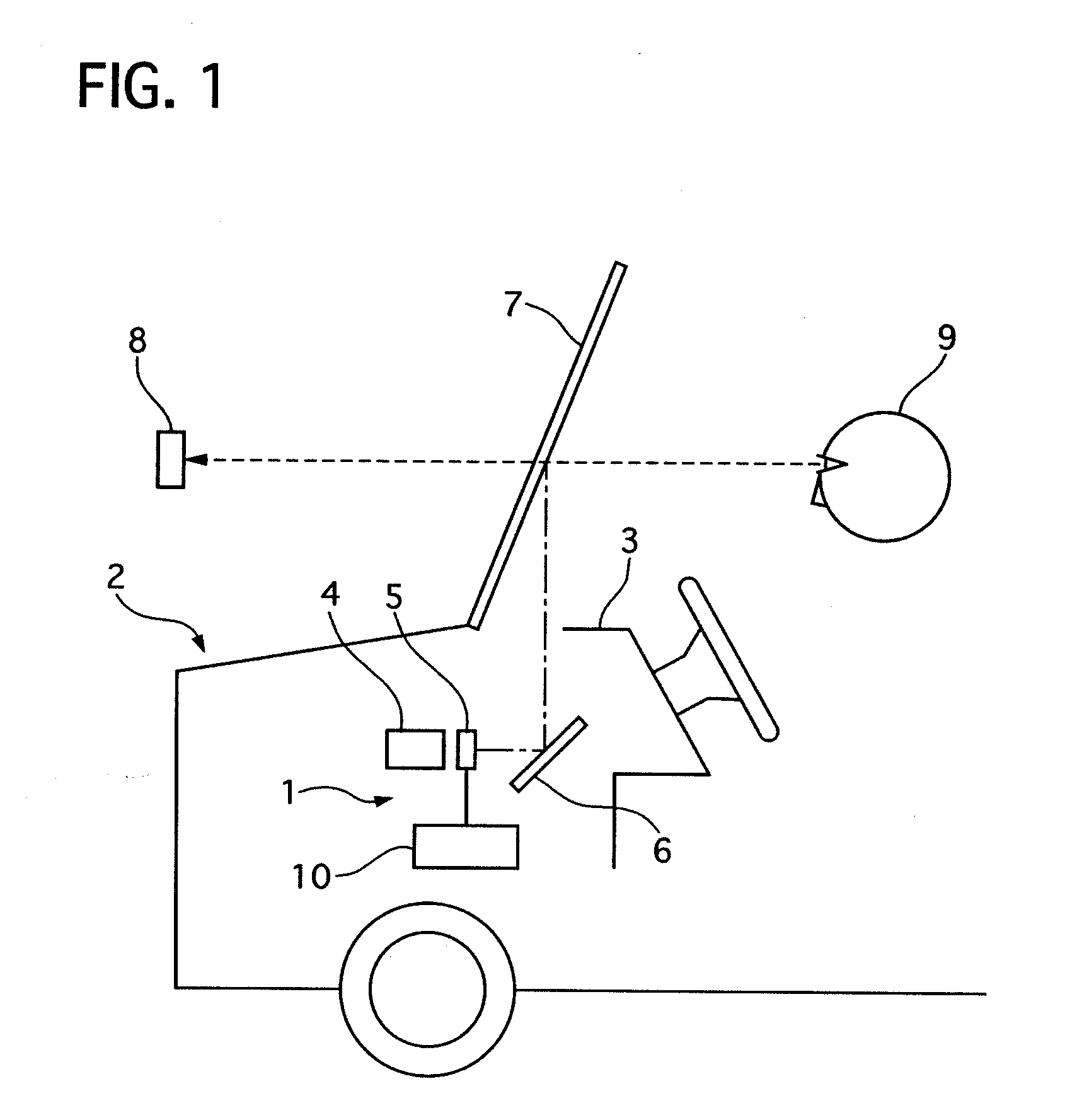
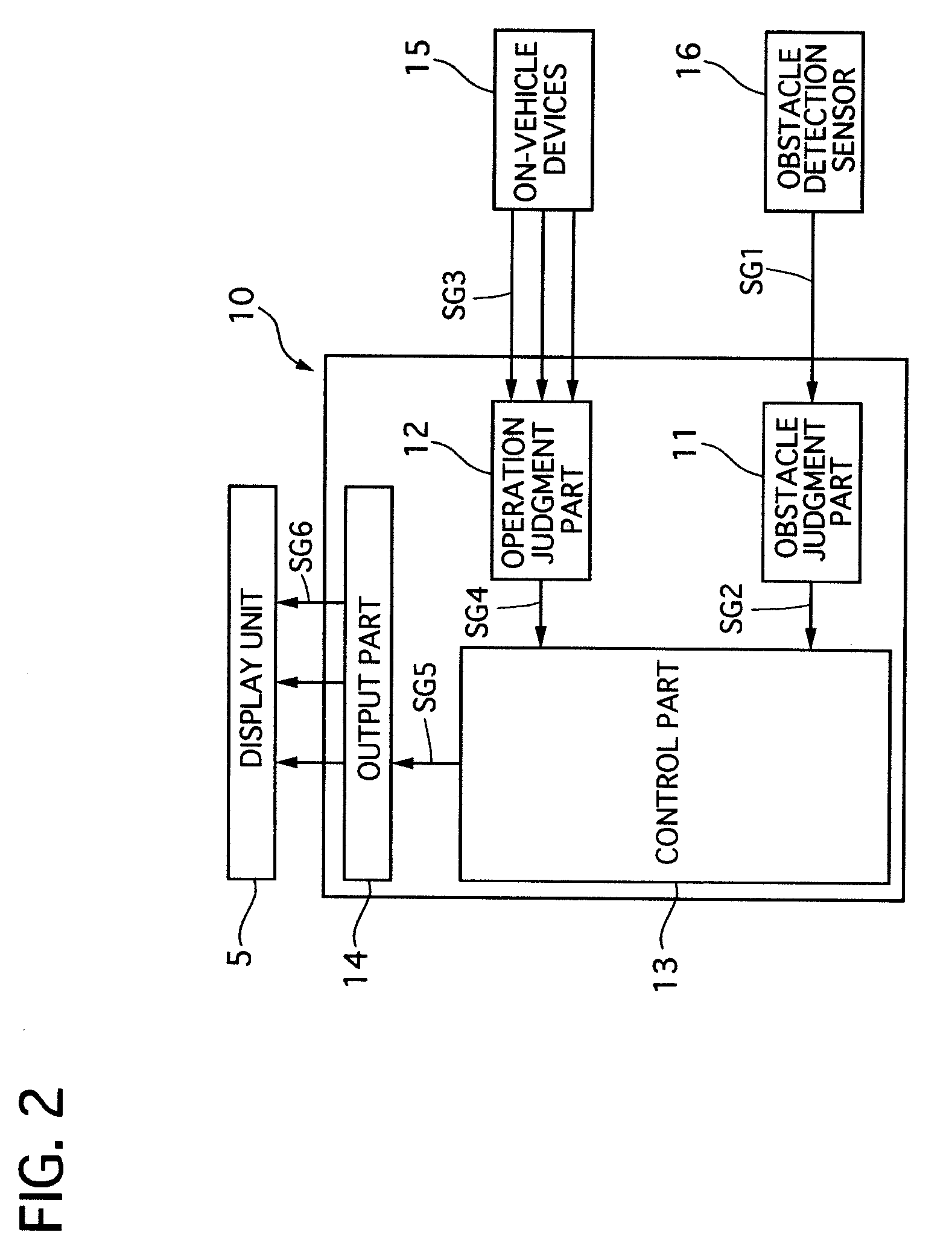
[0018]Referring to FIG. 1 and FIG. 2 of the drawings, there is shown a first preferred embodiment of a head-up display device according to the present invention.

[0019]The head-up display device 1 of the first embodiment is used for a motor vehicle 2, and it is installed in an instrument panel 3. The head-up display device 1 includes a light source 4, a liquid crystal display (LCD) 5, a mirror 6 and a display controller 10.

[0020]The light source 4 is capable of projecting light to the LCD 5, where the LCD 5 produces light with information such as a vehicle speed and others including an alarm for an obstacle in front of the motor vehicle 2. The light is reflected on the mirror 6 toward a front windshield 7 to show virtual images 8 and an alarm display image P, so that a dri...


PUM


Abstract

A head-up display device includes a light source, a display unit for producing display virtual images including an alarm display image, a mirror for reflecting the light to show the alarm display image in a field of front view of a driver, at least one on-vehicle device that the driver operates, a visual-line shift detecting means and a display position shifting means. The mirror reflects the light representing the alarm display image so that a driver can see the alarm display image in a display area that is set on one of a front windshield and a combiner in front of the driver and in a field of front vision of the driver. The visual-line shift detecting means detects a visual line shift of the driver from a usual forward visual range of the driver toward the on-vehicle device that the driver operates. The display position shifting means shifts positions of the display area to a position between the usual forward visual range and a portion / part, of the on-vehicle device at operation, which the driver watches during the operation when the visual-line shift detecting means detects the visual line shift from the usual forward visual range toward the on-vehicle device.

Description

BACKGROUND OF THE INVENTION[0001]1. Field of the Invention[0002]The present invention relates to a head-up display device, for a vehicle, that provides a driver with information through a virtual image projected on a combiner, front windshield or the like in a driver's direct line of sight.[0003]2. Description of the Related Art[0004]A conventional head-up display device for vehicles is disclosed in Japanese Patent Application Laying-Open publication No. 2001-357498. This conventional head-up display device includes an obstacle detecting means for detecting an obstacle in front of a driver, a regard point detecting means for detecting a point of regard of the driver, a projector for projecting a virtual display image representing various information to a driver, and a display changing means for changing the information represented by the virtual display image according to the movement of the point of regard and also for changing a size of a display area according to a vehicle runnin...

Claims


Application Information

Patent Timeline
Patent Type & Authority Applications(United States)
IPC IPC(8): B60Q1/00
CPCB60K35/00G02B27/01G02B2027/0187G02B2027/0183G02B2027/0159B60K35/60B60K2360/785B60K35/235
Inventor HIOKI, SHINJIRO
Owner CALSONIC KANSEI CORP
Learn More