Image processing apparatus, image processing method, and image processing program product

Active Publication Date: 2009-06-11
OLYMPUS CORP
View PDF7 Cites 44 Cited by
  • Summary
  • Abstract
  • Description
  • Claims
  • Application Information

AI Technical Summary

Problems solved by technology

Thus, an accuracy of an organ determination deteriorates.
However, the current situation is that no effective s

Method used


Image

  • Image processing apparatus, image processing method, and image processing program product
  • Image processing apparatus, image processing method, and image processing program product
  • Image processing apparatus, image processing method, and image processing program product

Examples


first embodiment

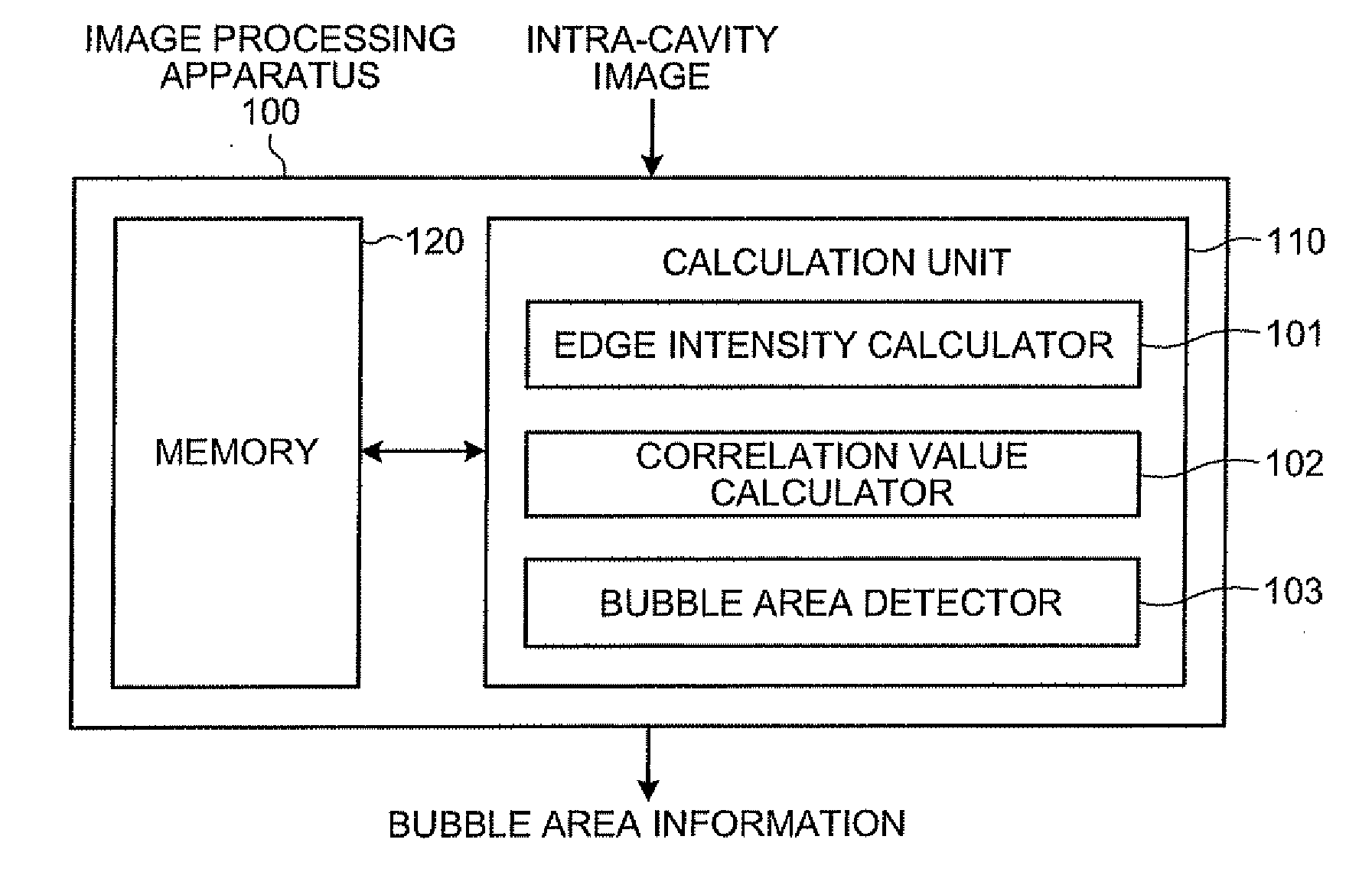
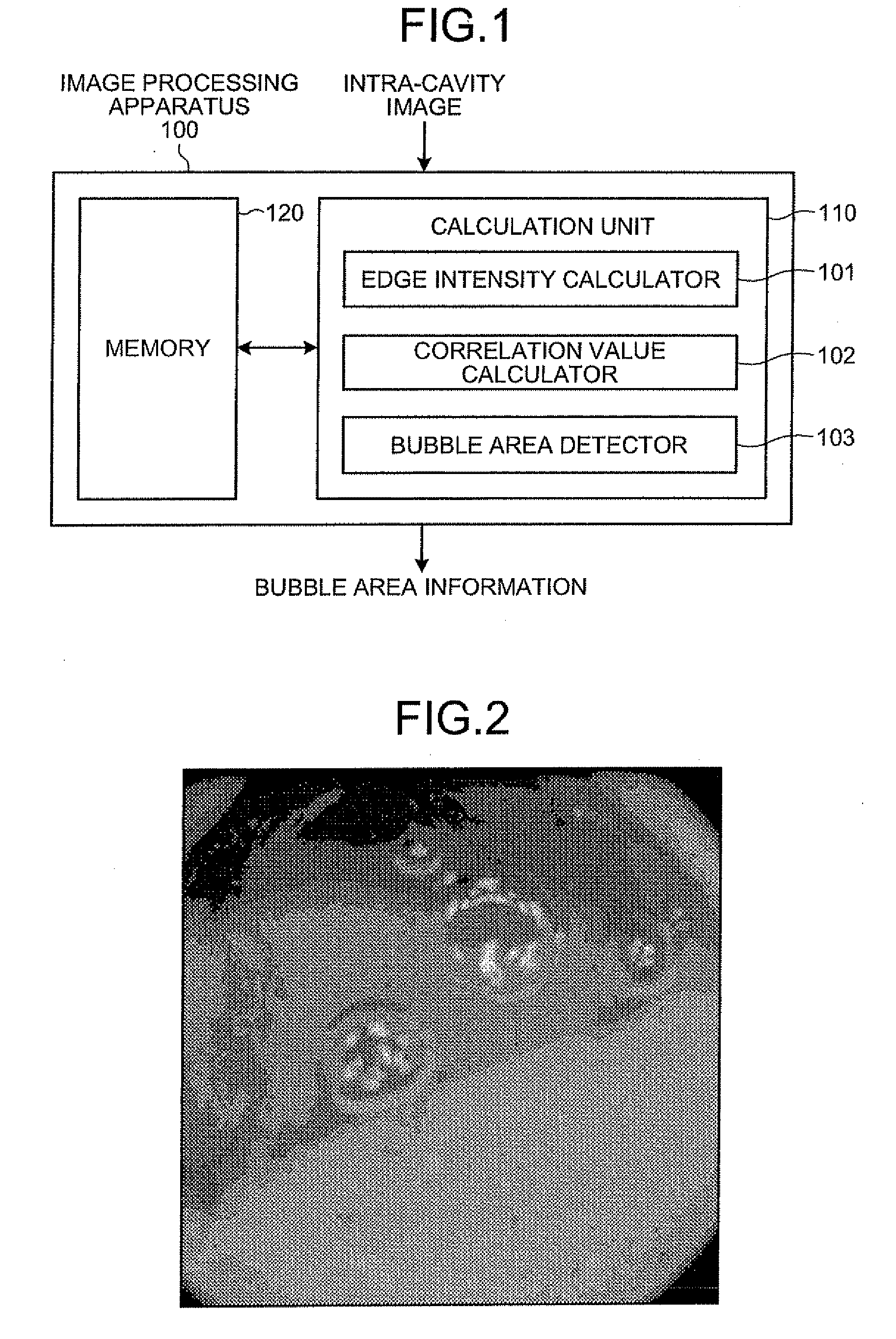
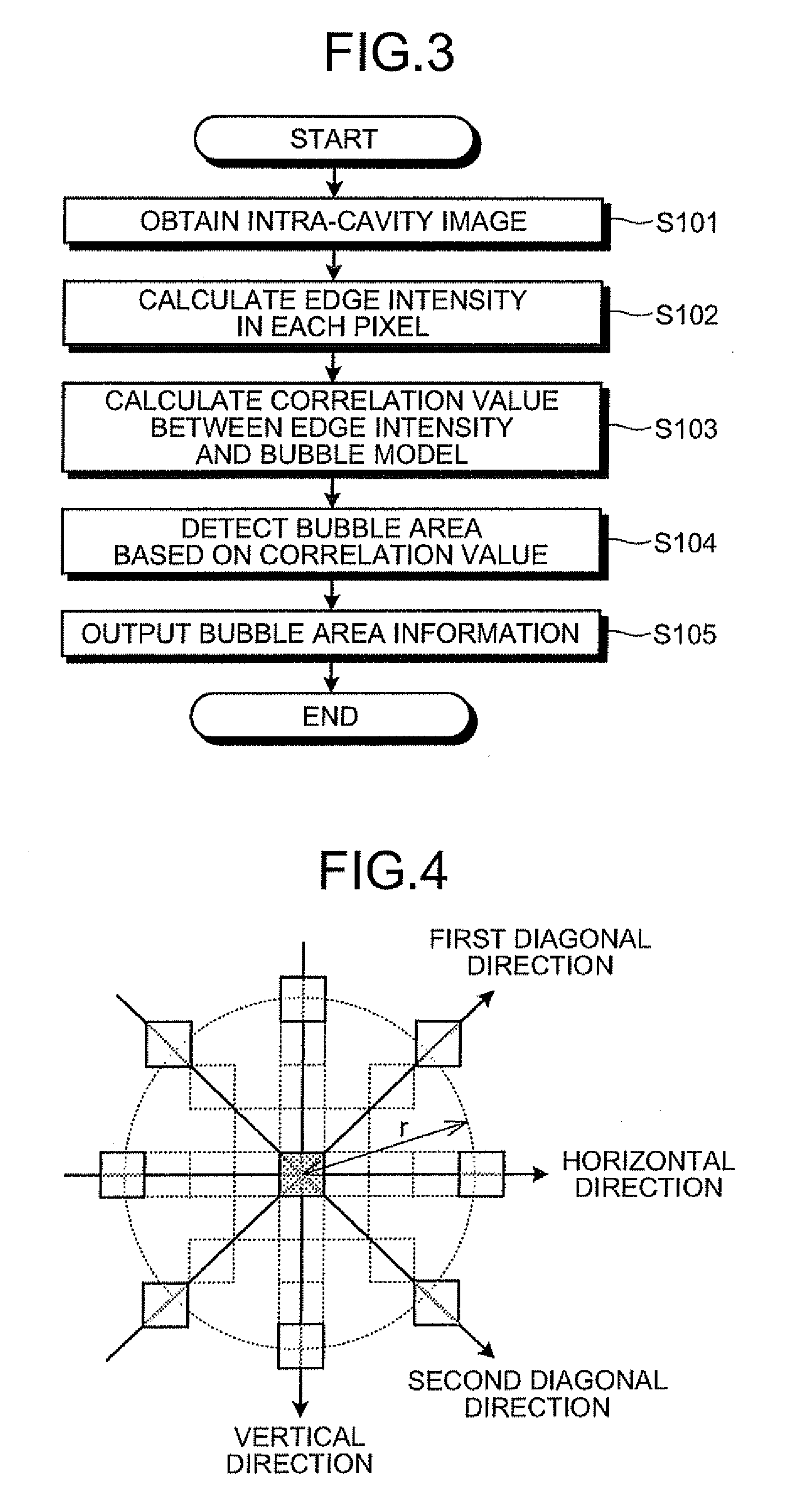
[0040]FIG. 3 is a schematic flowchart of a processing executed by the calculation unit 110 of the image processing apparatus 100 according to the An image processing procedure will be explained below in contrast with the structure shown in FIG. 1.

[0041]First of all, the calculation unit 110 obtains an intra-cavity image as a processing subject (step S101). Next, the edge intensity calculator 101 calculates an edge intensity of a pixel of the obtained intra-cavity image (step S102). While there are various methods for calculating the edge intensity, a method of using a processing of a quadratic differentiation for each direction will be explained here. FIG. 4 is an explanatory view of directions of a quadratic differentiation calculation in the edge intensity calculation. First, a quadratic differentiation in a horizontal direction dH, a quadratic differentiation in a vertical direction dV, a quadratic differentiation in a first diagonal direction dD1, and a quadratic differentiatio...

second embodiment

[0067]In the image processing apparatus 200 described above, since a bubble area in an image is detected based on, in addition to the correlation value between the calculated edge intensity and the bubble model, the result of dividing the image into areas based on an edge in the intra-cavity image, more accurate detection, with a correspondence to a contour edge of a bubble, of the bubble area can be realized. Thus, even in a case where the bubble area is present in the vicinity of a diseased site, the image processing apparatus 200 can be made good use of for more properly detecting a diseased site and the like without detecting the diseased site inclusively as the bubble area.

[0068]The processing procedure shown in FIGS. 3, 14, and the like performed by each of the edge intensity calculators 101 and 201, the correlation value calculators 102 and 202, the area divider 203, the bubble area detectors 103 and 204, and the morphologic processor 205 may be realized by making an image p...


PUM


Abstract

An image processing apparatus includes an edge intensity calculator which calculates an edge intensity of a pixel in an image; and a correlation value calculator which calculates a correlation value between the calculated edge intensity and a bubble model set in advance based on characteristics of a bubble image. The apparatus also includes a bubble area detector which detects a bubble area based on the calculated correlation value.

Description

CROSS-REFERENCE TO RELATED APPLICATIONS[0001]This application is a continuation of PCT international application Ser. No. PCT / JP2007 / 057924 filed on Apr. 10, 2007 which designates the United States, incorporated herein by reference, and which claims the benefit of priority from Japanese Patent Applications No. 2006-147316, filed on May 26, 2006, incorporated herein by reference.BACKGROUND OF THE INVENTION[0002]1. Field of the Invention[0003]The present invention relates to an image processing apparatus, an image processing method, and an image processing program product which detect a bubble area present in an image, and specifically to an image processing apparatus and an image processing program product which detect a bubble area present in an image captured in a body cavity.[0004]2. Description of the Related Art Japanese Patent Application Laid-Open No. 2004-337596 discloses, as an image processing on an intra-cavity image, a processing of determining an organ based on average c...

Claims


Application Information

Patent Timeline
IPC IPC(8): G06K9/00G06K9/40
CPCA61B1/041G06T5/20G06T7/0085G06T2207/30004G06T7/408G06T2207/10068G06T7/0091G06T7/13G06T7/155G06T7/90
Inventor KANDA, YAMATO
Owner OLYMPUS CORP
Why Eureka
Try Eureka