Golf club grip alignment using laser aligning device
- Summary
- Abstract
- Description
- Claims
- Application Information
AI Technical Summary
Problems solved by technology
Method used
Image
Examples
Embodiment Construction
—FIGS. 1A, 1B, AND 1C
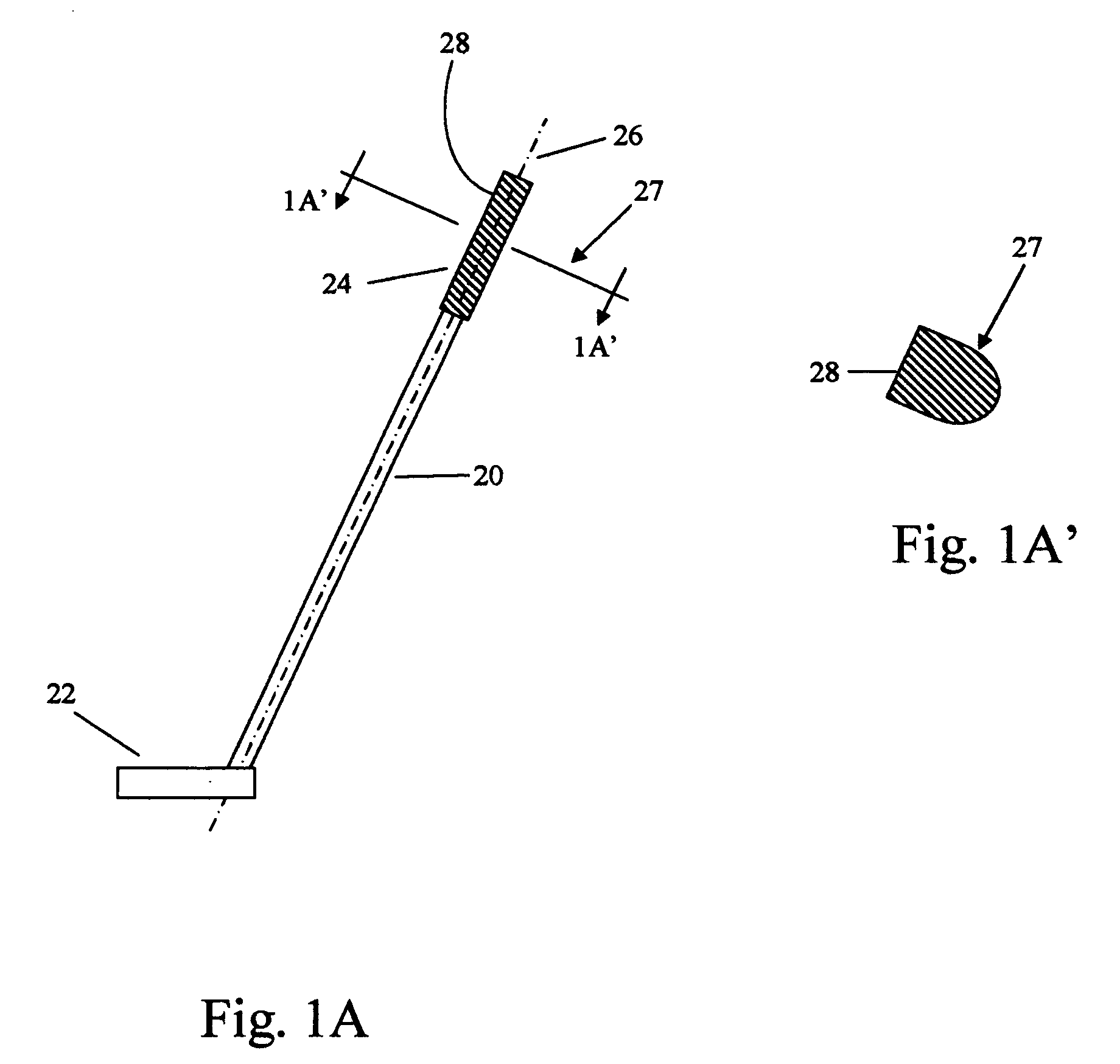
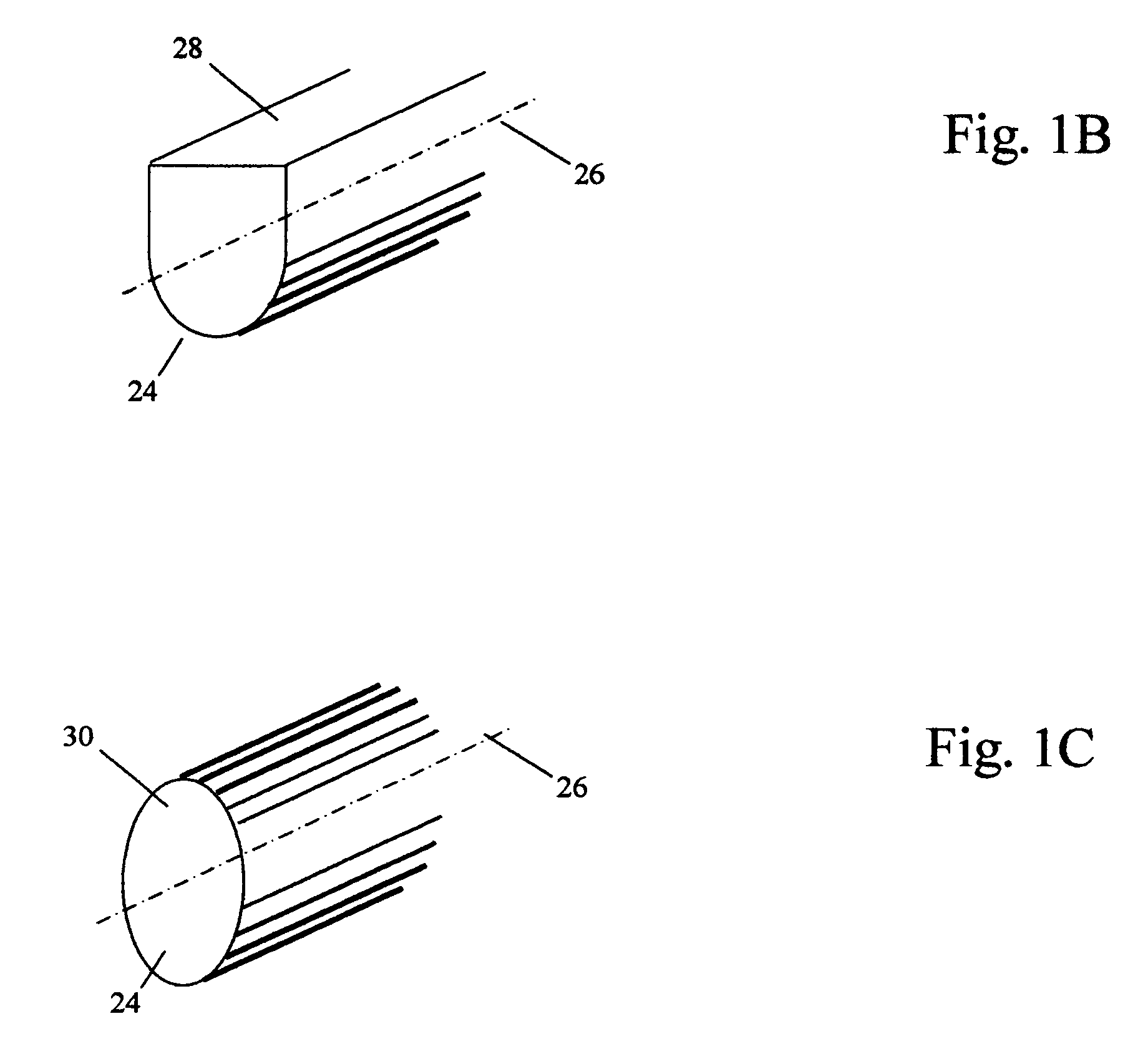
[0021]FIG. 1A shows golf club (preferably a putter) comprises a shaft 20, a club head 22 connected to shaft 20, and a grip 24 mounted on shaft 20. At the grip end, shaft 20 is cylindrical (i.e., it has a circular cross-section) and has a shaft axis 26. As shown in FIG. 1A′, the grip's cross-section 27 of a putter has a flat side 28. Flat surface 28 of FIGS. 1A and 1A′ is perpendicular to the plane of paper. The face of club head 22 is parallel to the plane of the paper in FIG. 1A. Thus surface 28 is perpendicular to the face of club head 22 (ball-hitting surface). FIG. 1B shows more detail of the grip portion of the club. In other golf clubs, grip 24 may have an oval cross-section 30 as shown in FIG. 1C. The alignment of oval-shaped grip will be discussed later.
DETAILED DESCRIPTION—FIGS. 2A and 2B
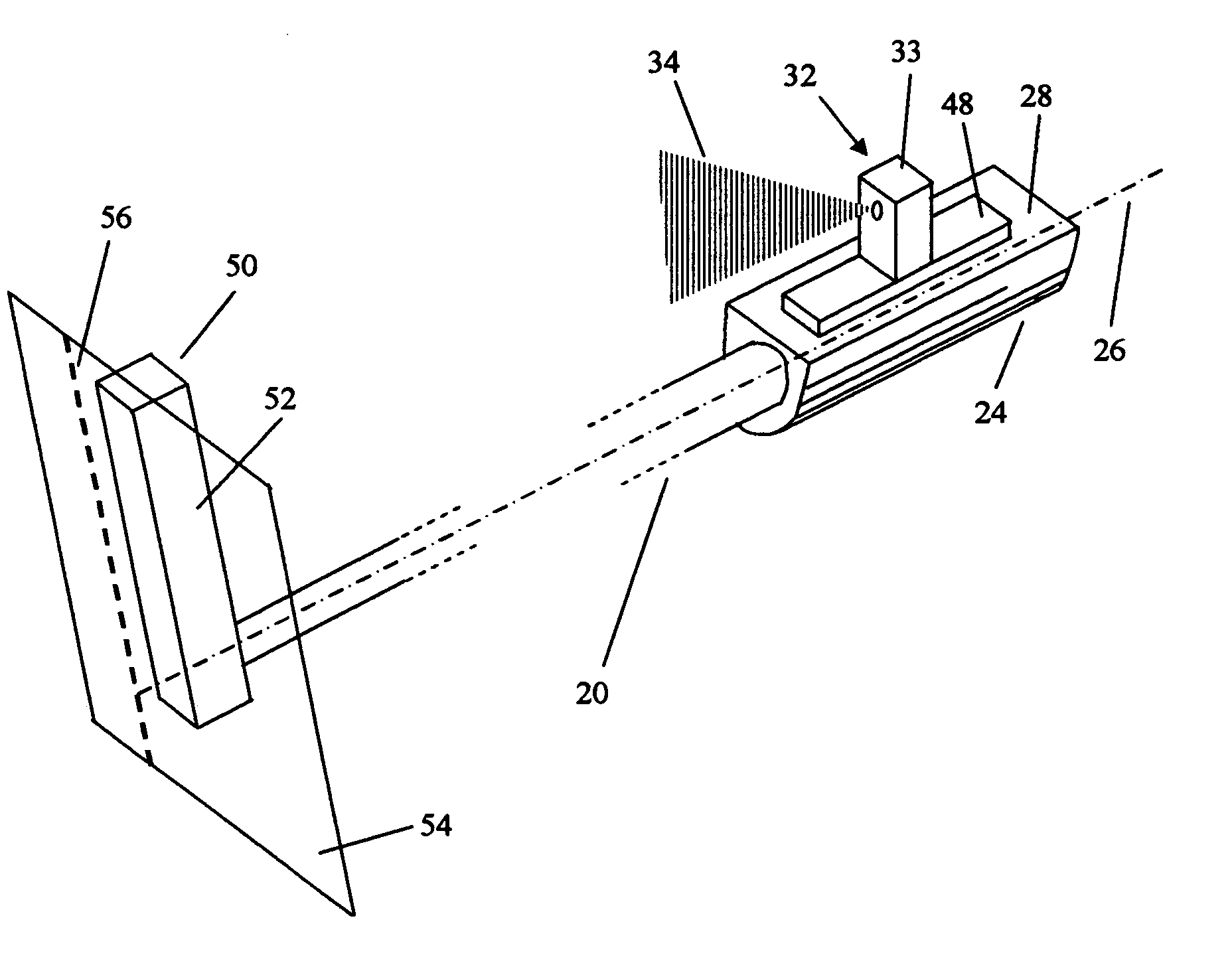
[0022]FIGS. 2A and 2B are diagrammatic views which illustrate some principles and geometry of laser aligning. A laser aligner 32 is positioned on a horizontal plane 36....
PUM
 Abstract
Description
Claims
Application Information
 - R&D Engineer
- R&D Manager
- IP Professional
- Industry Leading Data Capabilities
- Powerful AI technology
- Patent DNA Extraction
Browse by: Latest US Patents, China's latest patents, Technical Efficacy Thesaurus, Application Domain, Technology Topic, Popular Technical Reports.
© 2024 PatSnap. All rights reserved.Legal|Privacy policy|Modern Slavery Act Transparency Statement|Sitemap|About US| Contact US: help@patsnap.com


