Method of and system for producing images of objects using planar laser illumination beams and image detection arrays

a technology of image detection array and laser illumination beam, which is applied in the direction of electromagnetic radiation sensing, exposure control, instruments, etc., can solve the problems of wasting heat, large, heavy and expensive, and reducing the efficiency of scanning devices, so as to avoid shortcomings and drawbacks.

Inactive Publication Date: 2002-08-29
METROLOGIC INSTR
View PDF0 Cites 29 Cited by
  • Summary
  • Abstract
  • Description
  • Claims
  • Application Information

AI Technical Summary

Benefits of technology

0011] Accordingly, a primary object of the present invention is to provide an improved method of and system for illuminating the surface of objects during image formation and detection operations and

Problems solved by technology

Most prior art CCD-based image scanners, employed in conveyor-type package identification systems, require high-pressure sodium, metal halide or halogen lamps and large, heavy and expensive parabolic or elliptical reflectors to produce sufficient light intensities to illuminate the large depth of field scanning fields supported by such industrial scanning systems.
The balance of the output illumination power is simply wasted in the form of heat.
However, even with such improvements in LED

Method used


Image

  • Method of and system for producing images of objects using planar laser illumination beams and image detection arrays
  • Method of and system for producing images of objects using planar laser illumination beams and image detection arrays
  • Method of and system for producing images of objects using planar laser illumination beams and image detection arrays

Examples


embodiment 1

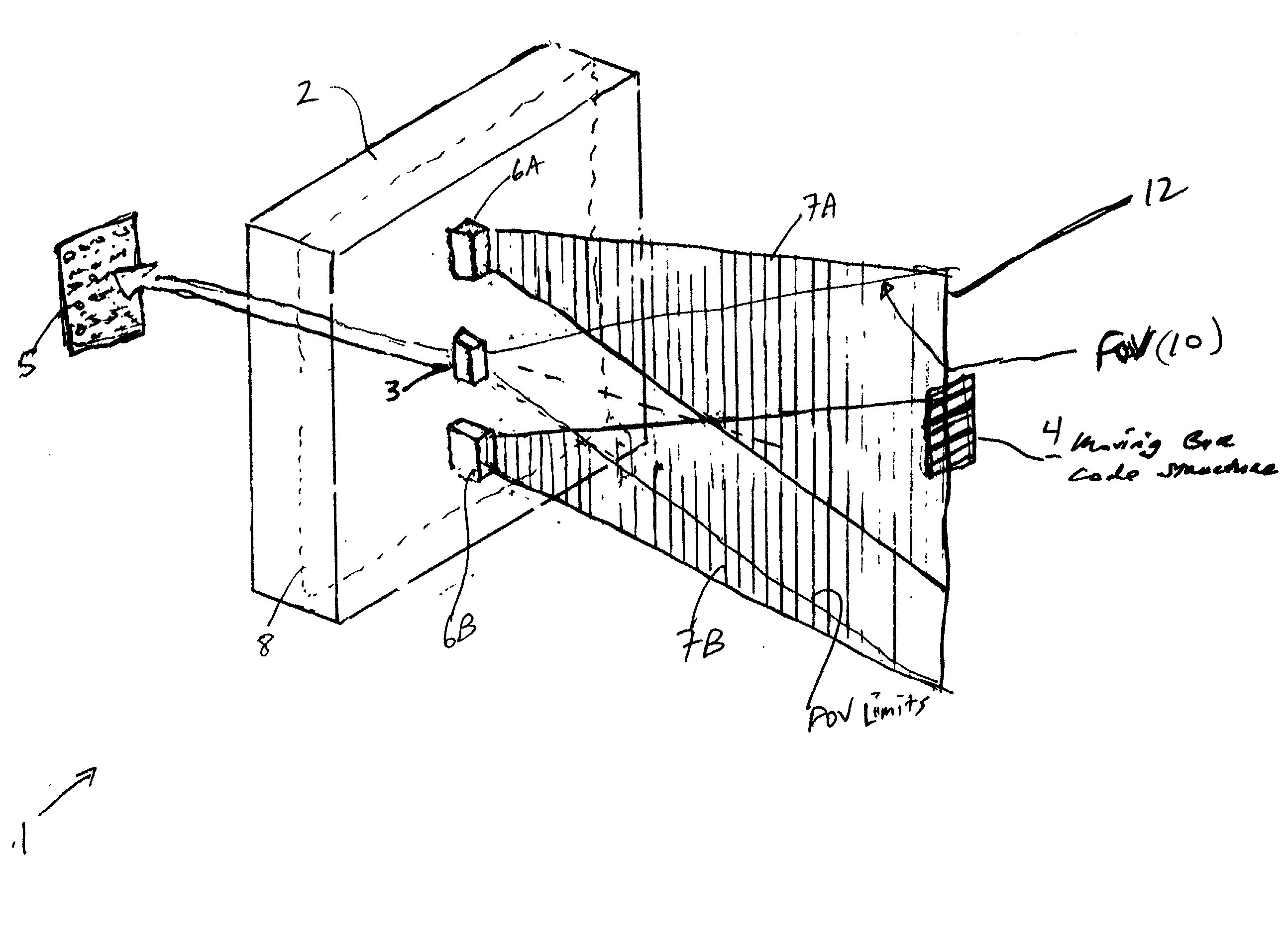
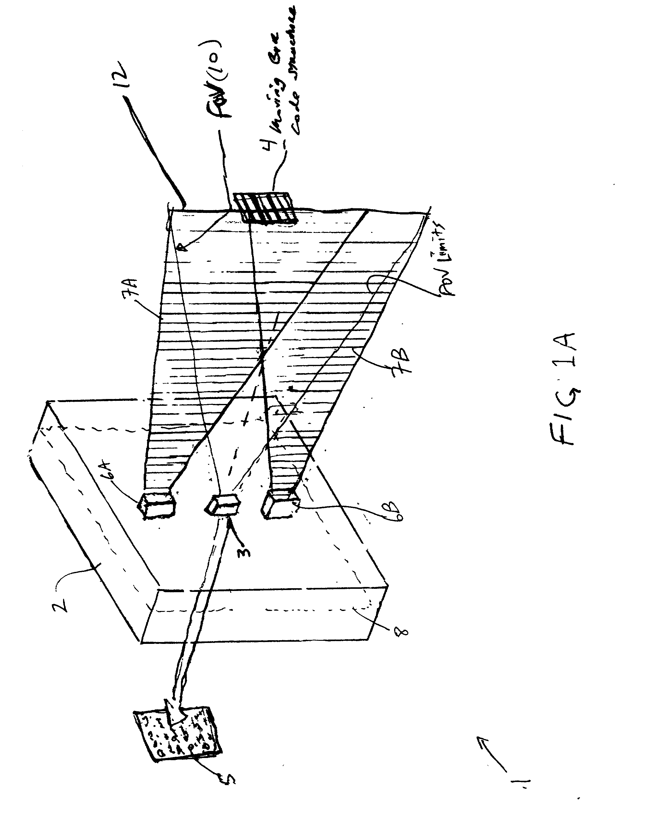
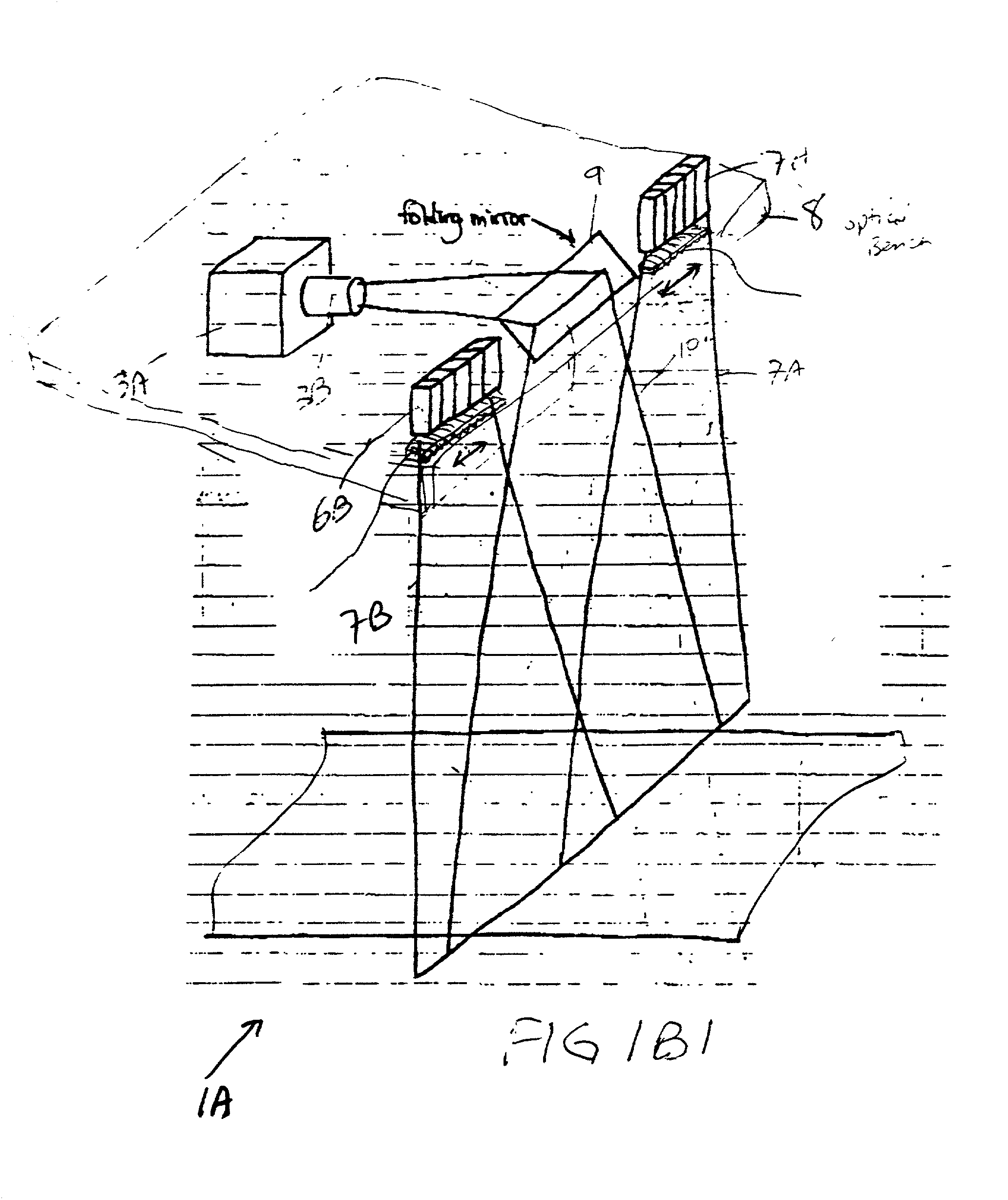
[0365] In accordance with the present invention, the planar laser illumination arrays 6A and 6B, the linear image formation and detection module 3, the folding / sweeping FOV mirror 9', and the planar laser illumination beam folding / sweeping mirrors 37A' and 37B' employed in this generalized system embodiment, are fixedly mounted on an optical bench or chassis 8 so as to prevent any relative motion (which might be caused by vibration or temperature changes) between: (i) the image forming optics (e.g. imaging lens) within the image formation and detection module 3 and the FOV folding / sweeping mirror 9' employed therewith; and (ii) each planar laser illumination module (i.e. VLD / cylindrical lens assembly) and the planar laser illumination beam folding / sweeping mirrors 37A' and 37B' employed in this PLIIM system configuration. Preferably, the chassis assembly should provide for easy and secure alignment of all optical components employed in the planar laser illumination arrays 6A' and 6B...

embodiment 40

[0370] In accordance with the present invention, the planar laser illumination arrays 6A and 6B, the linear image formation and detection module 3', and any non-moving FOV and / or planar laser illumination beam folding mirrors employed in any configuration of this generalized system embodiment, are fixedly mounted on an optical bench or chassis so as to prevent any relative motion (which might be caused by vibration or temperature changes) between: (i) the image forming optics (e.g. imaging lens) within the image formation and detection module 3' and any stationary FOV folding mirrors employed therewith; and (ii) each planar laser illumination module (i.e. VLD / cylindrical lens assembly) and any planar laser illumination beam folding mirrors employed in the PLIIM system configuration. Preferably, the chassis assembly should provide for easy and secure alignment of all optical components employed in the planar laser illumination arrays 6A and 6B as well as the image formation and detec...

embodiment 120

[0510] Referring now to FIGS. 9 and 10, a unitary package identification and dimensioning system of the first illustrated embodiment 120 will now be described in detail.

[0511] As shown in FIG. 10, the unitary system 120 of the present invention comprises an integration of subsystems, contained within a single housing of compact construction supported above the conveyor belt of a high-speed conveyor subsystem 121, by way of a support frame or like structure. In the illustrative embodiment, the conveyor subsystem 121 has a conveyor belt width of at least 48 inches to support one or more package transport lanes along the conveyor belt. As shown in FIG. 10, the unitary system comprises four primary subsystem components, namely: (1) a LADAR-based package imaging, detecting and dimensioning subsystem 122 capable of collecting range data from objects on the conveyor belt using a pair of multi-wavelength (i.e. containing visible and IR spectral components) laser scanning beams projected at ...


PUM


Abstract

Methods of and systems for illuminating objects using planar laser illumination beams having substantially-planar spatial distribution characteristics that extend through the field of view (FOV) of image formation and detection modules employed in such systems. Each planar laser illumination beam is produced from a planar laser illumination beam array (PLIA) comprising an plurality of planar laser illumination modules (PLIMs). Each PLIM comprises a visible laser diode (VLD, a focusing lens, and a cylindrical optical element arranged therewith. The individual planar laser illumination beam components produced from each PLIM are optically combined to produce a composite substantially planar laser illumination beam having substantially uniform power density characteristics over the entire spatial extend thereof and thus the working range of the system. Preferably, each planar laser illumination beam component is focused so that the minimum beam width thereof occurs at a point or plane which is the farthest or maximum object distance at which the system is designed to acquire images, thereby compensating for decreases in the power density of the incident planar laser illumination beam due to the fact that the width of the planar laser illumination beam increases in length for increasing object distances away from the imaging optics. By virtue of the present invention, it is now possible to use both VLDs and high-speed CCD-type image detectors in conveyor, hand-held and hold-under type scanning applications alike, enjoying the advantages and benefits that each such technology has to offer, while avoiding the shortcomings and drawbacks hitherto associated therewith.

Description

CROSS-REFERENCE TO RELATED U.S. APPLICATIONS[0001] This is a Continuation-in-Part of copending application Ser. No. ______ entitled "Method Of And System For Producing Images Of Objects Using Planar Laser Illumination Beams And Image Detection Arrays" filed Nov. 24, 2000 under 37 C.F.R. 1.10 (Express Mail No. EL701906400US); International Application PCT / US99 / 06505 filed Mar. 24, 1999, published as WIPO WO 99 / 49411; International Application PCT / US99 / 28530 filed Dec. 2, 1999, published as WIPO Publication WO 00 / 33239; copending application Ser. No. 09 / 452,976 filed Dec. 2, 1999; application Ser. No. 09 / 327,756 filed Jun. 7, 1999, which is a Continuation-in-Part of application Ser. No. 09 / 305,896 filed May 5, 1999, which is a Continuation-in-Part of copending application Ser. No. 09 / 275,518 filed Mar. 24, 1999, which is a Continuation-in-Part of copending application Ser. No. 09 / 274,265 filed Mar. 22, 1999; Ser. No. 09 / 243,078 filed Feb. 2, 1999; Ser. No. 09 / 241,930 filed Feb. 2, 199...

Claims


Application Information

Patent Timeline
IPC IPC(8): G02B26/10G02B27/48G06K7/10H01S5/022H01S5/40
CPCB82Y15/00G02B26/10G02B27/48G06K7/10722G06K7/10732G06K7/10811H01S5/02248H01S5/4025H01S5/02325
Inventor TSIKOS, CONSTANTINE J.SCHNEE, MICHAEL D.ZHU, XIAOXUNAMUNDSEN, THOMASNAYLOR, CHARLES A.DOBBS, RUSSELL JOSEPHWIRTH, ALLANJANKEVICS, ANDREWKNOWLES, CARLS HARRY
Owner METROLOGIC INSTR
Why Eureka
Try Eureka