Apparatus and Methods of Repairing Bone Defects

a technology of apparatus and bone defects, applied in the field of apparatus and methods for repairing bone defects, can solve the problems that no related art discloses the use of cannulated screws to introduce filling cement or glue, and achieve the effect of fortifying the structural integrity of the bon

Inactive Publication Date: 2009-06-18
MIKOL EDWARD J
View PDF8 Cites 68 Cited by
  • Summary
  • Abstract
  • Description
  • Claims
  • Application Information

AI Technical Summary

Benefits of technology

[0008]In a fourth embodiment of the present invention, one or more cannulated screws are inserted through a plate into a long bone to secure the fixation of the plate to the bone. In accordance with this embodiment, the screws pass through the naturally occurring medullary cavi

Problems solved by technology

However, none of the related art discloses the use of can

Method used


Image

  • Apparatus and Methods of Repairing Bone Defects
  • Apparatus and Methods of Repairing Bone Defects
  • Apparatus and Methods of Repairing Bone Defects

Examples


first embodiment

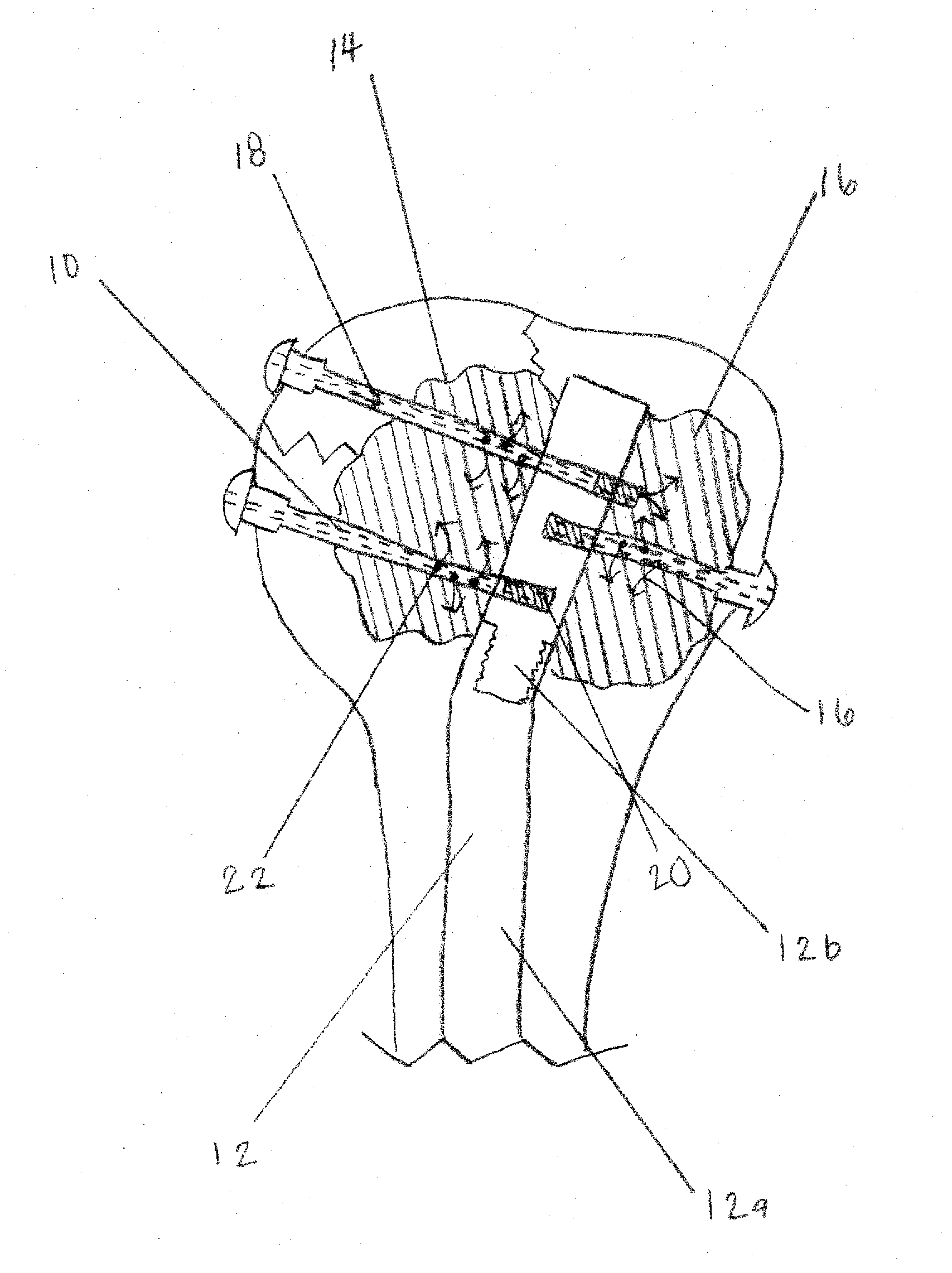
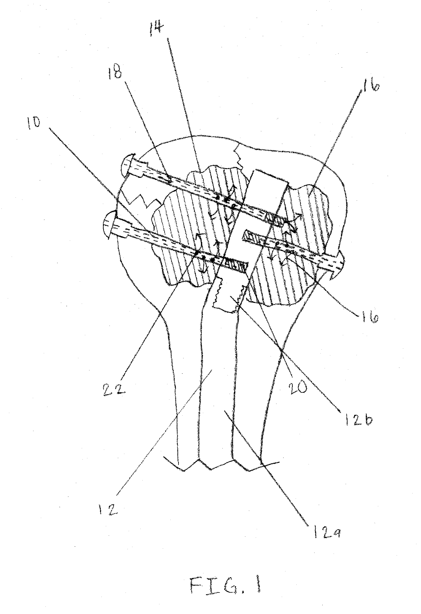
[0022]FIG. 1. illustrates the present invention. After an intramedullary nail 12 is installed in the proximal humerus with intraosseous void 14, one or more cannulated screws 10 are affixed to intramedullary nail 12. The intramedullary nail 12, as illustrated in FIG. 1, is an intramedullary rod having a stem member 12a and an extension member 12b. The cannulated screws 10 can be attached to extension member 12b or stem 12a. The threaded distal ends 20 of cannulated screws 10 can terminate in stem member 12a or extension member 12b, or they may pass through stem member 12a or extension member 12b to terminate inside the bone or osseous void. Further discussion of the intramedullary rod, including how stem member 12a and extension member 12b are connected, is found in U.S. Pat. No. 5,776,194, which was previously incorporated by reference in its entirety, and patents cited therein. However, it should be noted that the present invention is not limited simply to use in conjunction with ...

second embodiment

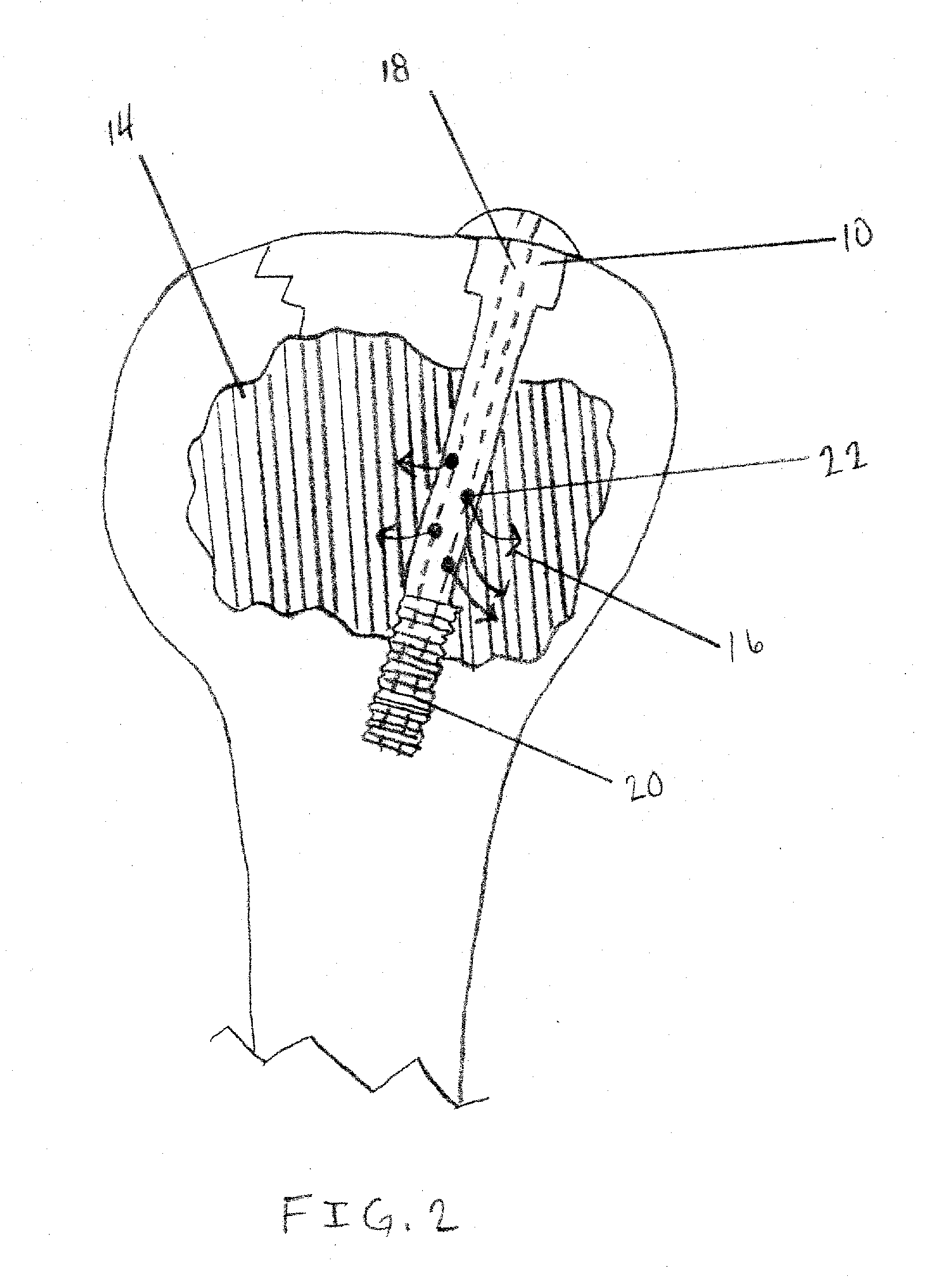
[0026]A second embodiment for treating a broken bone, such as a proximal humerus with intraosseous void 14, as illustrated in FIG. 2, uses one or more cannulated screws 10. More specifically, the one or more cannulated screws 10 contain exit slots 22 in addition to hollow longitudinal channel 18 and hollow threaded end 20. After one or more cannulated screws 10 are installed in the bone, a bioresorbable or non-bioresorbable glue or cement 16 can be injected into the proximal end of hollow longitudinal channel 18. Subsequently, the glue or cement 16 is extruded into intraosseous void 14 from hollow distal end 20 of hollow longitudinal channel 18 or exit slots 22. After curing, the one or more cannulated screws 10 are then incorporated into the cement construct, adding stability to the reconstructed humerus.

third embodiment

[0027]In the present invention, illustrated in FIG. 4, one or more cannulated screws 10 are inserted into a femur through a plate 30 affixed to the outside of the bone to secure a fracture at the femoral neck 32. At least one cannulated screw 10 slides through plate 30 and passes into femoral head 28. A bioresorbable or non-bioresorbable glue or cement 16 is deposited into the proximal end of cannulated screw 10 and through hollow longitudinal channel 18. If no osseous void or cavity exists, glue or cement 16 is extruded through exit slots 22 or hollow distal end 20 of hollow longitudinal channel 18 and subsequently interdigitates with the porous bone of femoral neck 32 or femoral head 28. If an osseous void or cavity does exist at the proximal end of the femur, glue or cement 16 is extruded through exit slots 22 or hollow distal end 20 of hollow longitudinal channel 18 and fills said osseous void or cavity. Upon curing, glue or cement 16 helps to strengthen the fixation of cannulat...


PUM


Abstract

An apparatus and method for repairing osseous defects in such bones as the humerus, femur, ulna and long bones. A first embodiment presents one or more cannulated screws affixed to an intramedullary nail, which is installed in a humerus having an intraosseous void. In a second embodiment, one or more cannulated screws alone are inserted into a proximal humerus having an intraosseous void. Other embodiments teach one or more cannulated screws inserted into a damaged femur and attached to a plate or medullary rod. Another embodiment presents a number of cannulated screws used to attach a plate to a fractured long bone. In a final embodiment, a cannulated screw is installed in damaged ulna. In all embodiments, a bioresorbable or non-bioresorbable cement is injected into a hollow channel of the cannulated screw and extruded into the bone to stabilize the weakened bone and secure the position of a fixation device.

Description

FIELD OF THE INVENTION[0001]This invention relates to an apparatus and method for repairing bone defects or augmenting the fixation of a device into or onto bone. In particular, the invention relates to using cannulated screws, either alone or in conjunction with a nail, plate, rod or other fixation device, to treat osseous voids or weaknesses or to secure fixation devices that may otherwise fail due to weak purchase in bone.BACKGROUND OF THE INVENTION[0002]Osseous voids, which threaten the structural integrity of a bone, are caused by trauma, infection, congenital malformation, tumor growth, or degenerative diseases. As discussed in U.S. Pat. No. 7,045,125, bone grafts are conventionally used to regenerate and heal the affected bone. Alternatively, as disclosed in the '125 patent, affected bones can be treated by filling the osseous voids with biologically active composites that are injected into the osseous voids.[0003]U.S. Pat. No. 5,776,194, which is incorporated herein by refer...

Claims


Application Information

Patent Timeline
IPC IPC(8): A61B17/58
CPCA61B17/7098A61B17/725A61B17/7258A61B17/8695A61B17/746A61B17/80A61B17/864A61B17/744
Inventor MIKOL, EDWARD J.
Owner MIKOL EDWARD J
Why Eureka
Try Eureka