
Removable dust receptacle for dust collector

a dust collector and dust receptacle technology, applied in the direction of cleaning filter means, cleaning equipment, separation processes, etc., can solve the problems of no pressing or locking or positioning device provided for pressing or locking or anchoring, and it is difficult to remove or disengage or move the dust collection barrel away from the dust collector, so as to achieve easy removal or disengagement or move away, easy and quick cleaning or dumped

Inactive Publication Date: 2009-06-25
CHANG TJER INDAL
View PDF10 Cites 12 Cited by
  • Summary
  • Abstract
  • Description
  • Claims
  • Application Information

AI Technical Summary

Benefits of technology

"The present invention is a vacuum or dust collector with a detachable dust collecting receptacle that can be easily removed or disengaged from the main collector for cleaning or dumping. The collector includes a manually operated device for securing the receptacle, and a cover for selectively closing or opening the receptacle. The actuating device can be a bar or a handle that moves the cover to close or open the receptacle. The housing includes a duct, a flexible member, and a casing with an orifice for connecting to a duct. The base includes a rail and the receptacle includes an anchor for sliding and moving relative to the base. The housing also includes a compartment for a fan device and a canister for receiving light weight dust. The technical effects of the invention include easy cleaning and maintenance of the vacuum or dust collector, and improved user experience."

Problems solved by technology

However, after the dirt or dust drawing or collecting operations, or when it is required to clean or dump the dust collection barrel, it will be difficult to remove or disengage or move the dust collection barrel away from the dust collector.
In addition, no pressing or locking or positioning devices have been provided for pressing or locking or anchoring the cover to the dust collection barrel such that the cover may have a good chance to be disengaged from the dust collection barrel while conducting the vacuuming operations.

Method used


Image

  • Removable dust receptacle for dust collector
  • Removable dust receptacle for dust collector
  • Removable dust receptacle for dust collector

Examples


Embodiment Construction

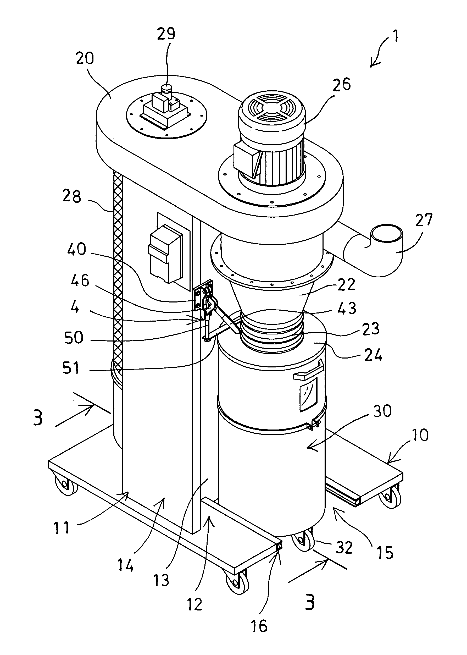
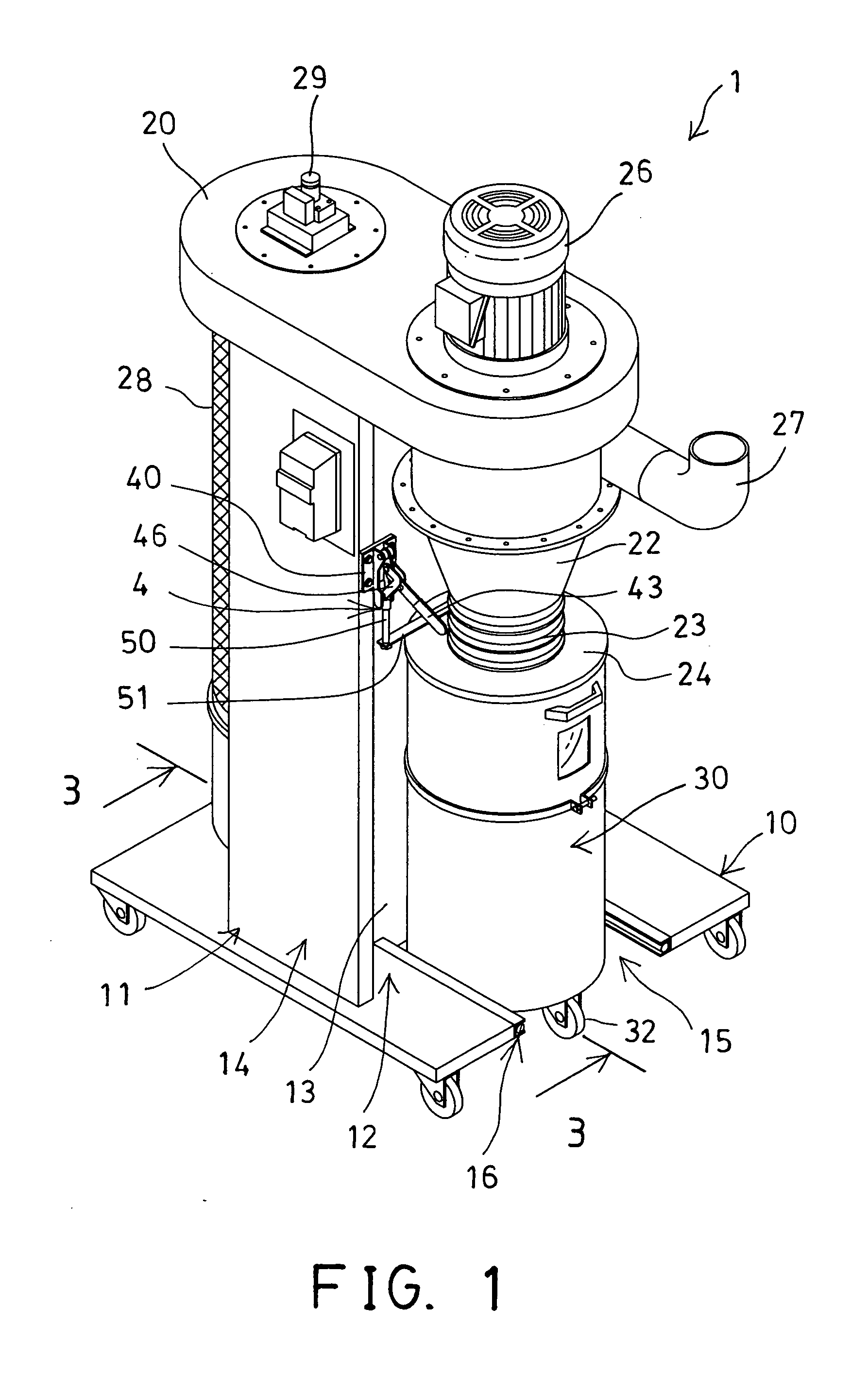
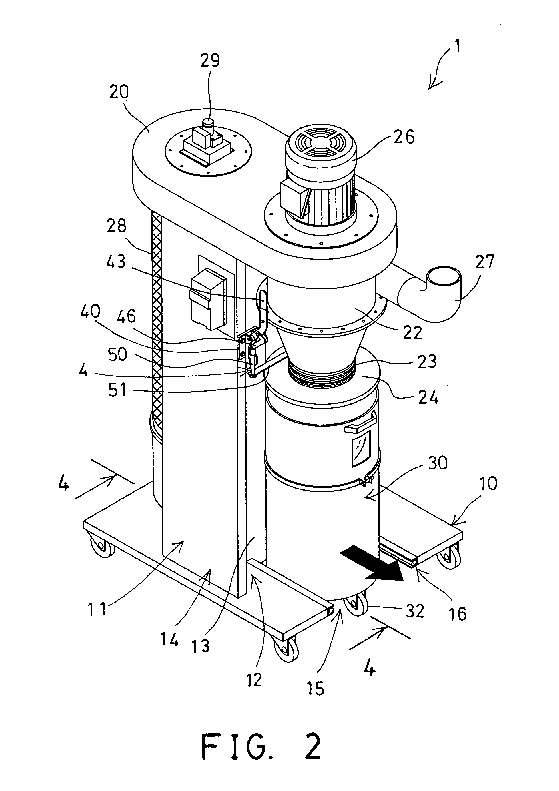
[0028]Referring to the drawings, and initially to FIGS. 1-5, a dust or vacuum collector 1 in accordance with the present invention comprises a base 10 including an upright support or post 11 extended upwardly therefrom, and including a chamber 12 formed in the post 11 and defined by a partition 13 and two side panels 14, and including an opening 15 formed in the base 10 for slidably receiving a dust collection barrel or dust collecting receptacle 30, and including a track or rail 16 formed or provided for on each side of the opening 15 of the base 10. The dust collecting receptacle 30 includes one or more (such as two) side rods or anchors 31 attached thereto or extended laterally and outwardly therefrom (FIG. 5) for slidably engaging with the tracks or rails 16 of the base 10 and for guiding the dust collecting receptacle 30 to slide or to move relative to the base 10.

[0029]The vacuum collector 1 further includes a housing 20 disposed on top of the post 11 and having a compartment ...


PUM

PropertyMeasurementUnit
flexibleaaaaaaaaaa
weightaaaaaaaaaa

Abstract

A dust collector includes a post extended from a base, a housing disposed on the post, a dust collecting receptacle, a cover coupled to the housing and disposed above the dust collecting receptacle for selectively closing the dust collecting receptacle or for selectively opening the dust collecting receptacle, and an actuating device for selectively actuating the cover to close the dust collecting receptacle, and for selectively moving the cover away from the dust collecting receptacle to open the dust collecting receptacle and to allow the dust collecting receptacle to be moved either away from or toward the base and to allow the dust to be easily dumped or removed from the dust collecting receptacle.

Description

BACKGROUND OF THE INVENTION[0001]1. Field of the Invention[0002]The present invention relates to a vacuum collector or dust collector, and more particularly to a vacuum collector or dust collector having a dust collection barrel or dust collecting receptacle detachably secured to the dust collector for allowing the dust collecting receptacle to be easily removed or disengaged or moved away from the dust collector and for allowing the dust received or collected within the dust collecting receptacle to be easily and quickly cleaned or dumped from the dust collecting receptacle.[0003]2. Description of the Prior Art[0004]Typical vacuum or dust collectors comprise an array of drum filters and a frame disposed in a permanent operative position proximate the array, and a number of longitudinal members operatively disposed on the frame for receiving and filtering and collecting the dirt, and suction nozzles extended from tubes for drawing and collecting the dirt.[0005]For example, U.S. Pat....

Claims


Application Information

Patent Timeline
Patent Type & Authority Applications(United States)
IPC IPC(8): A47L9/14
CPCB01D46/48
Inventor LIN, KUN YI
Owner CHANG TJER INDAL
Learn More