Coupling assembly with a core unit therein

Inactive Publication Date: 2009-07-02
TAIWAN VERTEX PRODN CORP
View PDF8 Cites 65 Cited by
  • Summary
  • Abstract
  • Description
  • Claims
  • Application Information

AI Technical Summary

Benefits of technology

[0005]The present invention will become more obvious from the following description when taken in connection with the accompa

Problems solved by technology

Nevertheless, there is no valve unit located between the male and female members so that during working, fluid flows through the pipes and the male and fema

Method used


Image

  • Coupling assembly with a core unit therein
  • Coupling assembly with a core unit therein
  • Coupling assembly with a core unit therein

Examples


Embodiment Construction

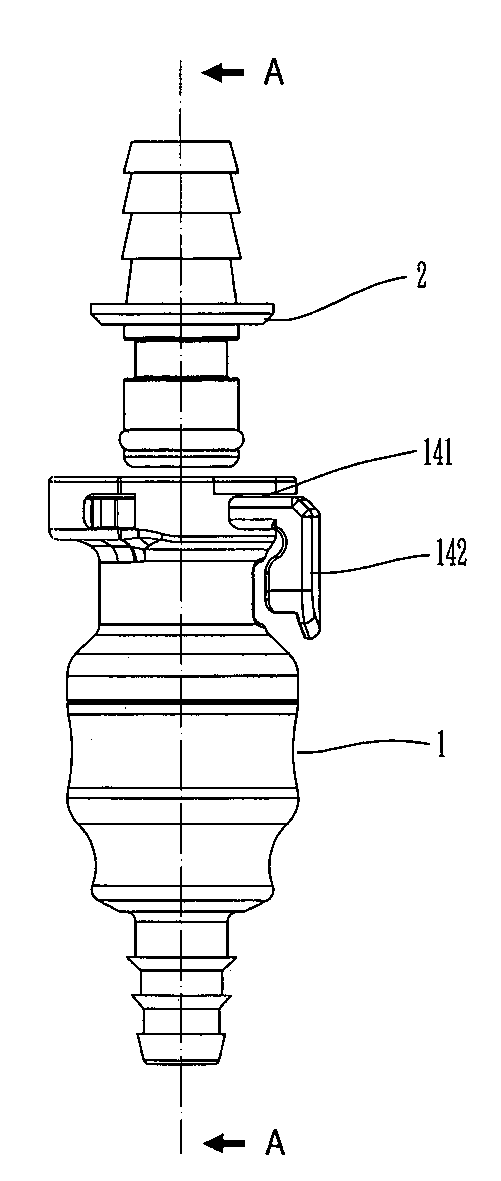
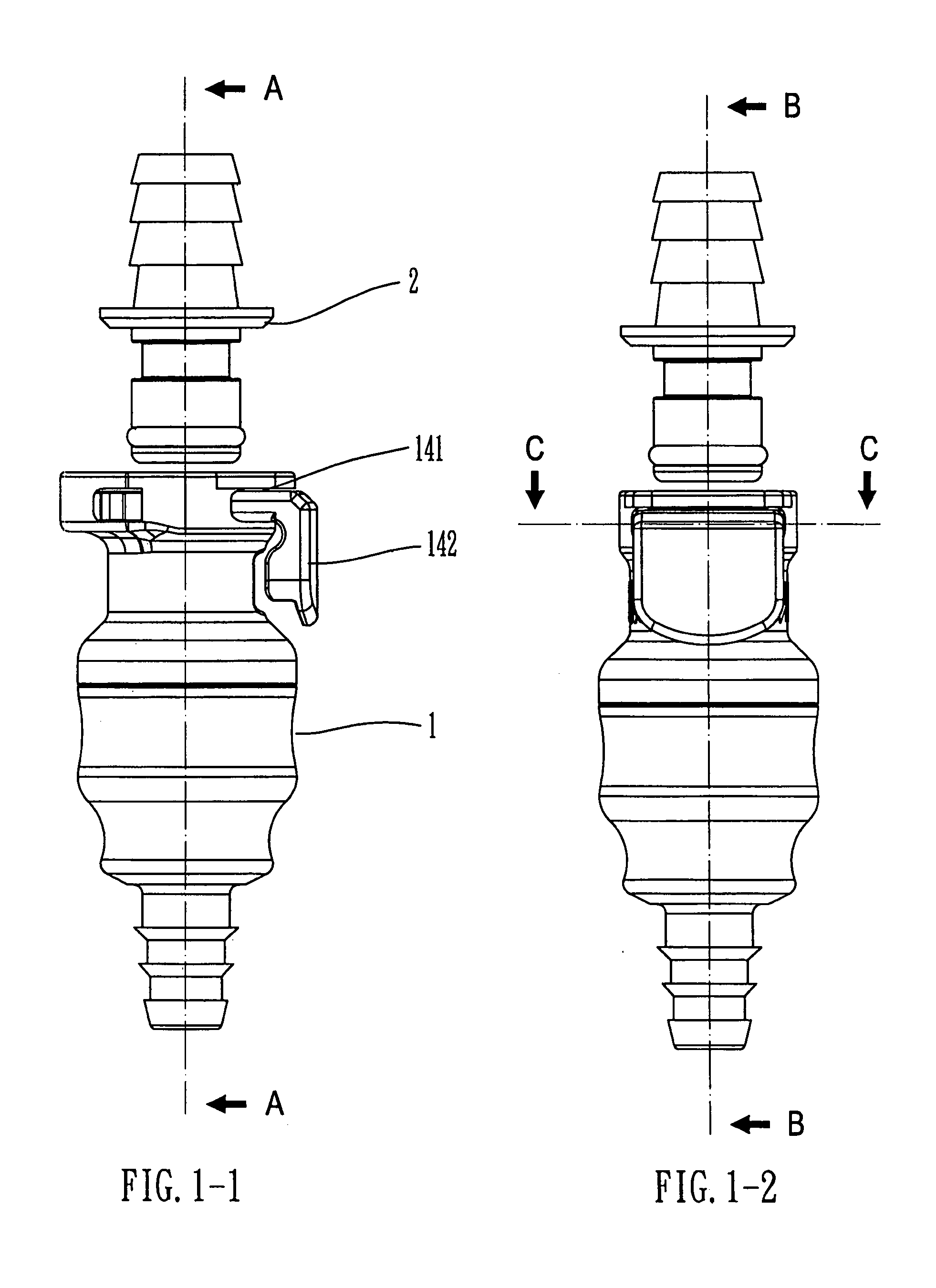
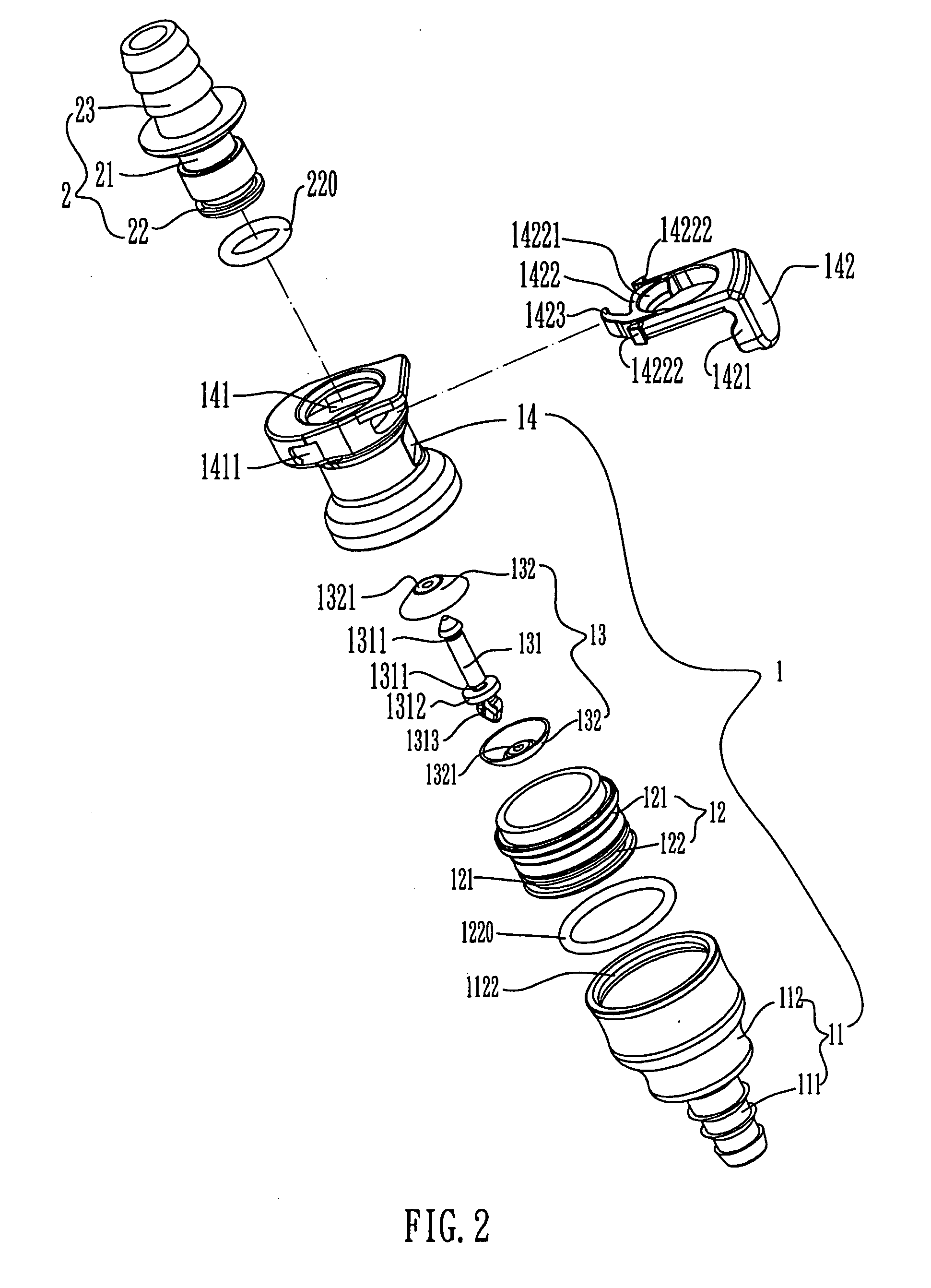
[0012]Referring to FIGS. 1-1, 1-2, 2 and 3, the coupling assembly for lower pressure piping system of the present invention comprises a female unit 1 and a male unit 2. The female unit 1 includes a connection member 11 which includes an enlarged connection end 112 and a barbed tube 111 extends from the connection end 112 so as to be connected with a pipe or hose (not shown). A support frame 1121 is located in the connection end 112 and a plurality of passages 11212 are defined around the support frame 1121. The passages 11212 communicate with the barbed tube 111. The connection end 112 includes a rib 1122 extending inward from an inner periphery thereof.

[0013]A sleeve 12 is engaged with the connection end 112 and includes a through hole 123 and a plurality of paths 124 defined through a lower end of the sleeve 12. The sleeve 12 includes upper and lower engaging flanges 121 on an outer periphery thereof and a groove 122 is defined in the outer periphery of the sleeve 12 so that a sea...


PUM


Abstract

A coupling assembly includes a female unit and a male unit which is removably connected with the female unit. A valve unit is located in the female unit and includes a core with two flexible disks on two ends thereof. A flange extends radially outward from a lower end of the core and is rested on a support frame in the female unit. The core extends through a through hole in a lower end of sleeve in the female unit. A plurality of paths are defined through the lower end of the sleeve so that by shifting the core to let either of two flexible disks to seal the paths in one direction, the direction of fluid flow can be controlled. The movement of the core is made by moving the sleeve.

Description

FIELD OF THE INVENTION[0001]The present invention relates to a coupling assembly with a valve unit in the female member so as to stop the fluid flow in either direction.BACKGROUND OF THE INVENTION[0002]A conventional coupling assembly known to applicant is disclosed in U.S. Pat. No. 5,104,158 which includes a male coupling member and a female coupling member and a clip member for connecting the male and female members. The clip member includes a tab portion so that the user can push the tab portion to release the male coupling member from the female coupling member. The disclosed coupling assembly allows the user to connect or release the male and female member quickly. Nevertheless, there is no valve unit located between the male and female members so that during working, fluid flows through the pipes and the male and female couplings and the user cannot stop the fluid to separate the male female coupling members when needed unless the source of the fluid is sealed or stopped.[0003...

Claims


Application Information

Patent Timeline
IPC IPC(8): F16L37/08
CPCF16L37/0841F16L37/38Y10T137/5153Y10T137/7771Y10T137/7779Y10T137/789
Inventor LIEN, CHIEN-PING
Owner TAIWAN VERTEX PRODN CORP
Why Eureka
Try Eureka