Image forming apparatus and image forming method
- Summary
- Abstract
- Description
- Claims
- Application Information
AI Technical Summary
Benefits of technology
Problems solved by technology
Method used
Image
Examples
first embodiment
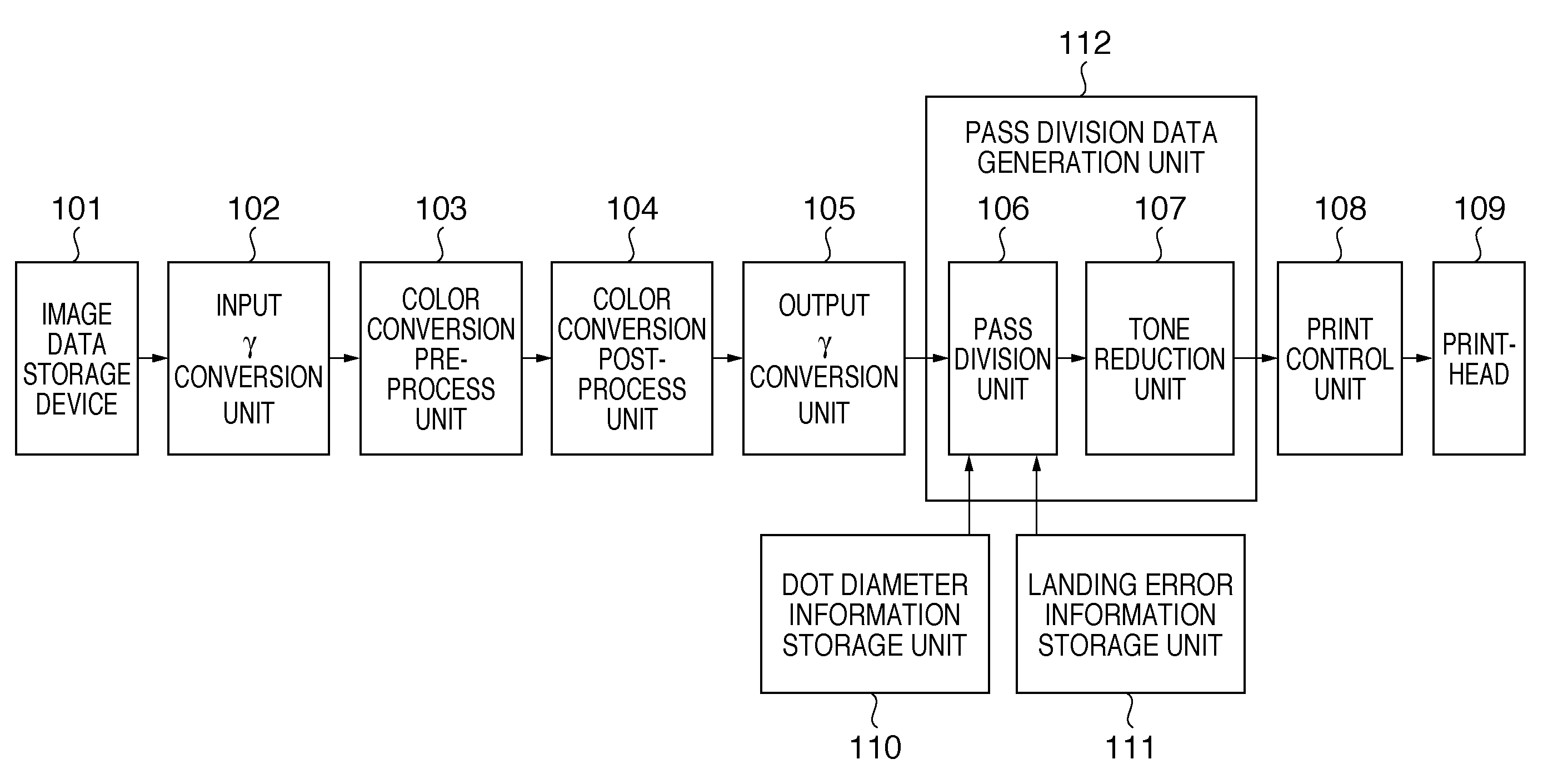
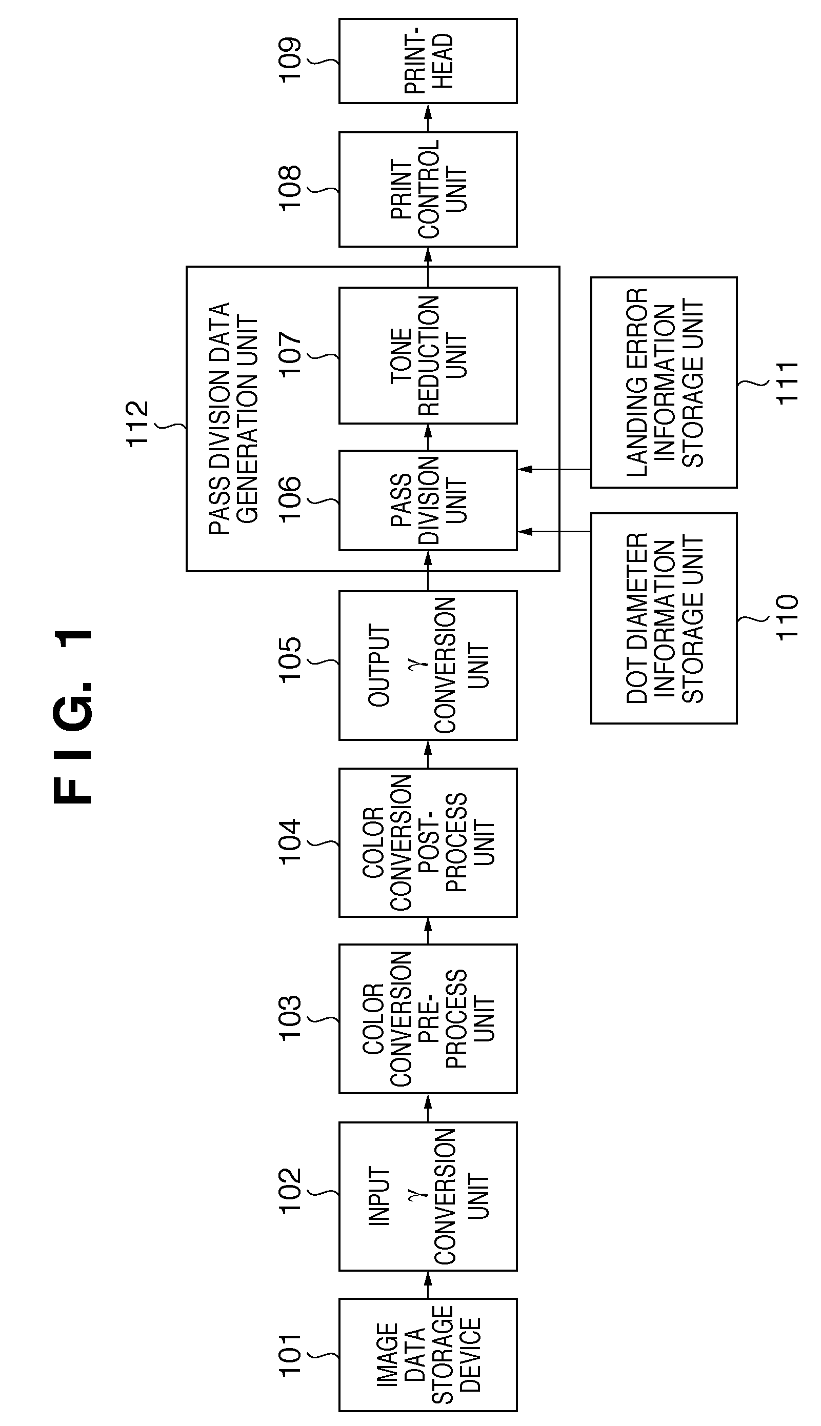
[0042]FIG. 1 is a block diagram showing the functional arrangement of an image forming apparatus 100 according to the first embodiment of the present invention. The image forming apparatus 100 forms a halftone image on a print medium by using a multipass process to scan a printhead N (N is an integer of 2 or more) times in a single area on the print medium and form dots by each scan operation. The image forming apparatus comprises functional units 101 to 109.
[0043]The image data storage device 101 stores multilevel image data transferred from a host computer, reads out data for each band, and inputs it to the input γ conversion unit 102. The input γ conversion unit 102γ-converts input image data into a linear luminance signal. The color conversion pre-process unit 103 performs RGB→RGB color conversion (color matching) by using a multilevel RGB→multilevel RGB lookup table. The color conversion post-process unit 104 performs RGB→CMYK color conversion (output device color separation) b...
second embodiment
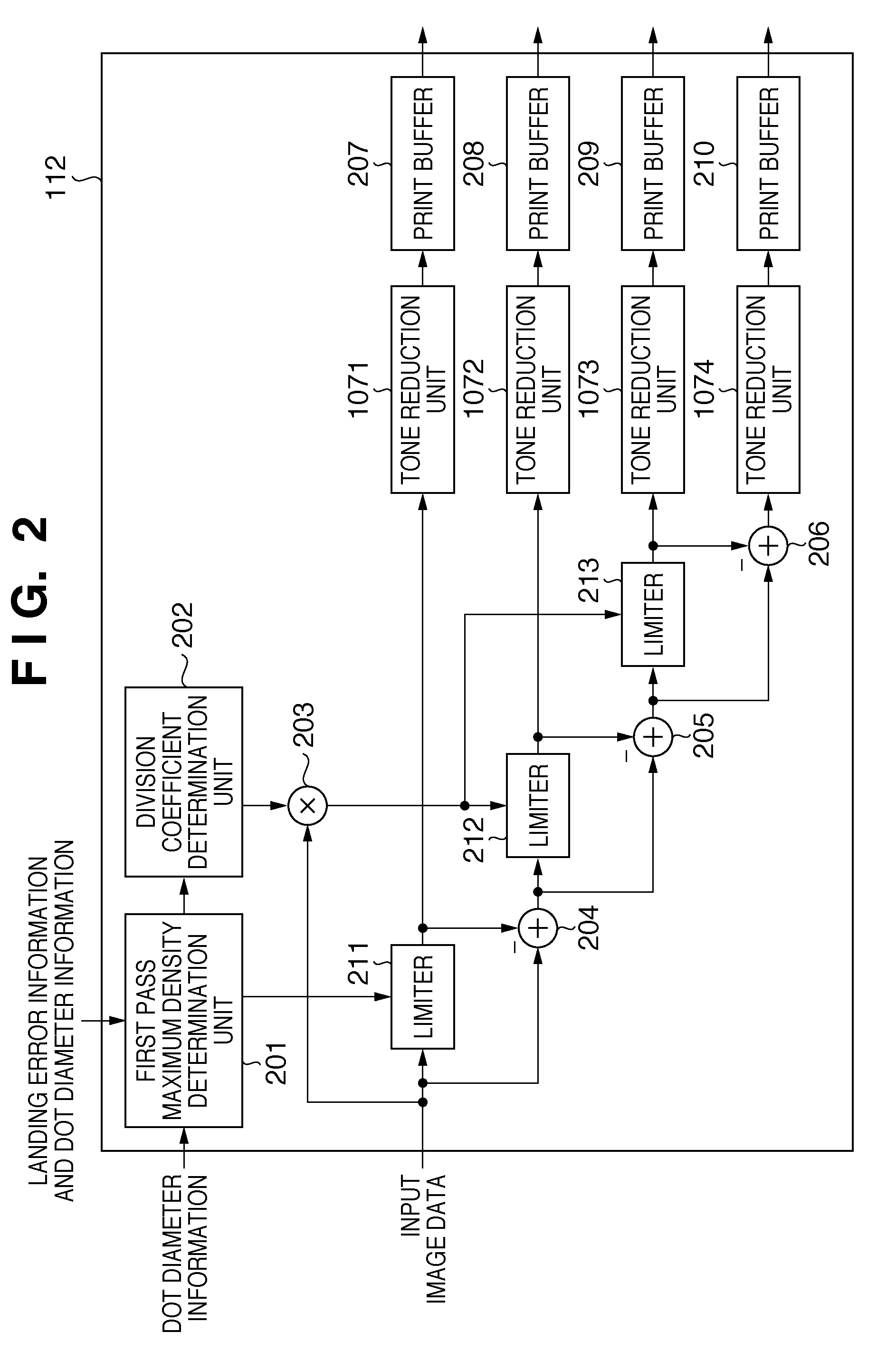
[0073]FIG. 10 is a block diagram showing the functional arrangement of a pass division data generation unit 112 according to the second embodiment of the present invention. The same reference numerals as those in the first embodiment denote the same parts, and a description thereof will not be repeated.
[0074]A division coefficient setting unit 301 divides input image data into the densities of respective passes. Multipliers 302, 303, 304, and 305 multiply input image data by a division coefficient determined by a division coefficient determination unit 202. An adder 306 adds an output from a subtracter 204 to that from the multiplier 305. Tone reduction units 307, 308, 309, and 310 convert the image signals of respective passes into the number of tones outputtable by the printhead.
[0075]In the second embodiment, the division coefficient setting unit 301, and multipliers 302, 303, 304, and 305 divide input image data into the densities of respective passes. For example, for 4-pass eq...
third embodiment
[0079]FIG. 11 is a block diagram showing the functional arrangement of a pass division data generation unit 112 according to the third embodiment of the present invention. The same reference numerals as those in the first and second embodiments denote the same parts, and a description thereof will not be repeated.
[0080]A first pass maximum density setting unit 311 sets, in a limiter 211, the maximum density of the first pass determined by a CPU (not shown) or the like. A division coefficient setting unit 312 sets the division coefficients of passes (second and third passes in the third embodiment) except the first and final passes. Multipliers 313 and 314 multiply the difference between input image data and the density of the first pass by the division coefficients set by the division coefficient setting unit 312. Subtracters 315 and 316 subtract the densities of the second and third passes from the difference between the density output by the first pass and input image data.
[0081]F...
PUM
 Abstract
Description
Claims
Application Information
 - R&D
- Intellectual Property
- Life Sciences
- Materials
- Tech Scout
- Unparalleled Data Quality
- Higher Quality Content
- 60% Fewer Hallucinations
Browse by: Latest US Patents, China's latest patents, Technical Efficacy Thesaurus, Application Domain, Technology Topic, Popular Technical Reports.
© 2025 PatSnap. All rights reserved.Legal|Privacy policy|Modern Slavery Act Transparency Statement|Sitemap|About US| Contact US: help@patsnap.com


