Image projection apparatus
- Summary
- Abstract
- Description
- Claims
- Application Information
AI Technical Summary
Benefits of technology
Problems solved by technology
Method used
Image
Examples
first embodiment
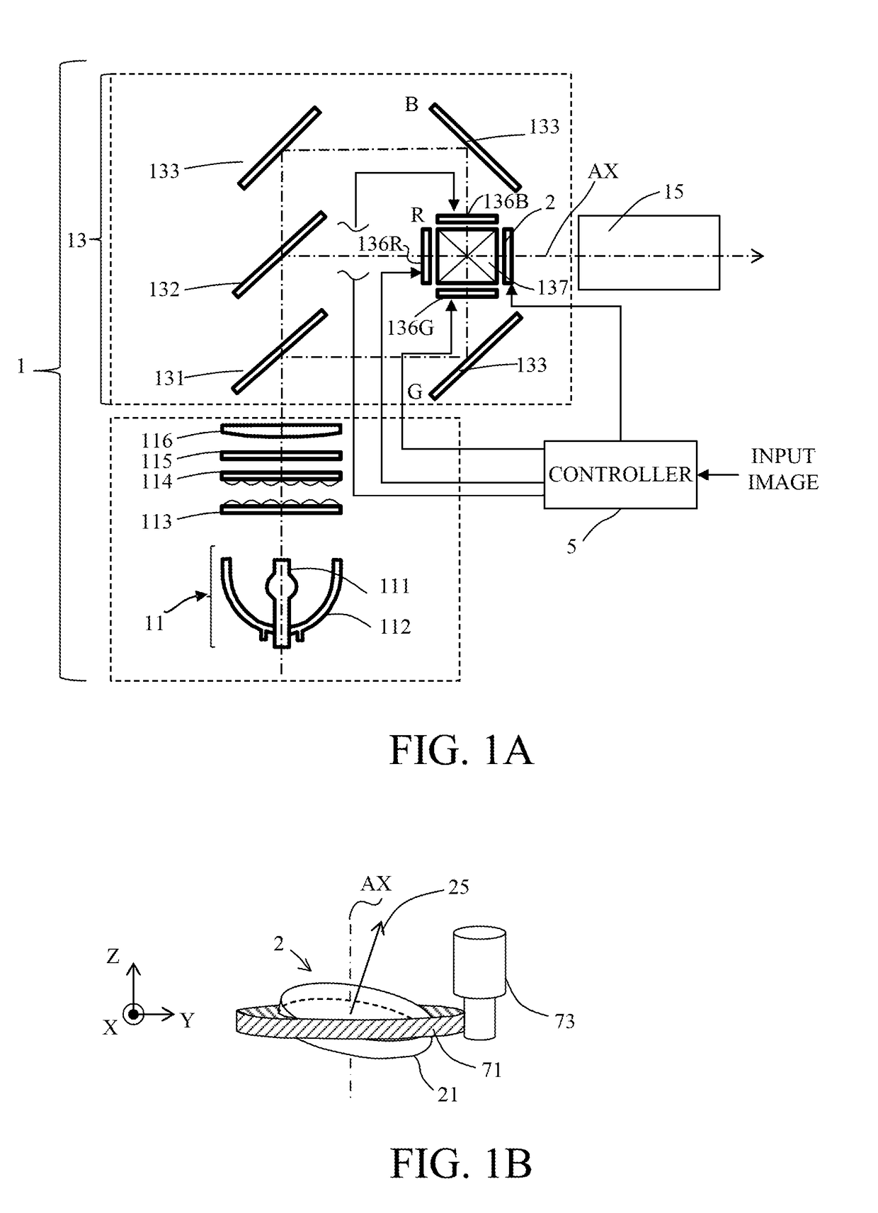
[0017]FIG. 1A illustrates an image projection apparatus (referred to as a “projector” hereinafter) according to a first embodiment of the present invention. The projector 1 includes a light source unit 11, a first lens array 113, a second lens array 114, a polarization conversion element 115, a condenser lens 116, a color separating and combining optical unit 13, and a projection lens 15.
[0018]The light source unit 11 includes a light source 111 and a reflector 112. A divergent light flux emitted from the light source 111 is converted into parallel light flux by the reflector 112, and goes to the first lens array 113. This embodiment uses an ultrahigh pressure mercury lamp for the light source 111. The light source 111 may use a halogen lamp, a light emitting diode (LED), a laser diode (LD), etc. Part of the light source unit 11 may use a wavelength conversion element, such as a fluorescent body, which converts a wavelength of light from the light source into another wavelength.
[001...
numerical example 1
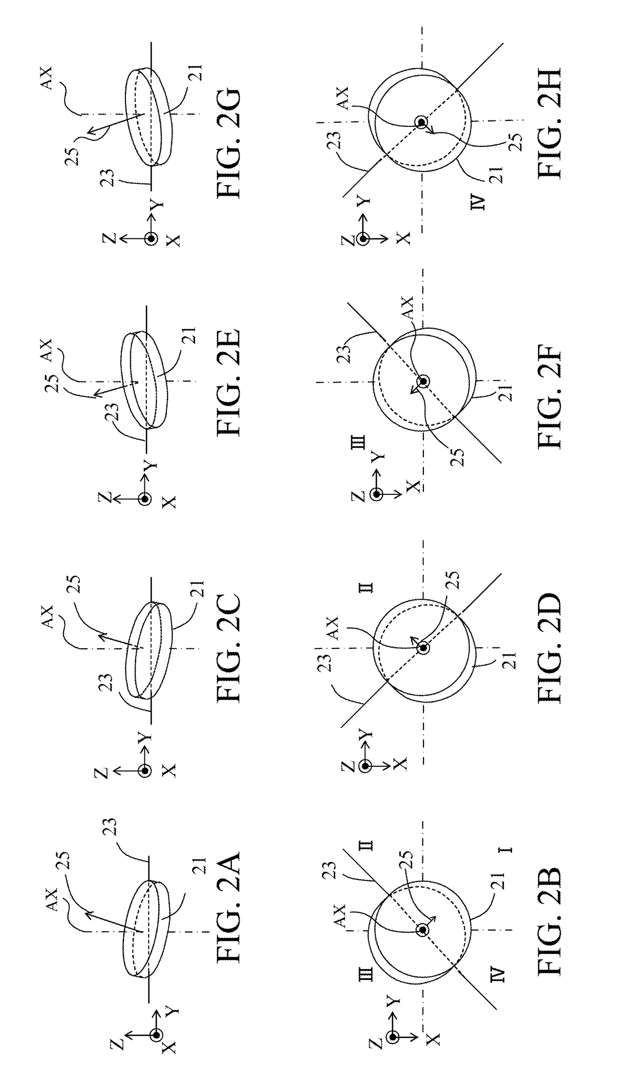
[0043]A description will be given of numerical example 1 as a concrete numerical example (simulation result) according to this embodiment. A 4K resolution liquid crystal panel with a pixel pitch of 3.8 μm (half pixel pitch of 2.69 μm in the diagonal direction) is used for the liquid crystal panel. The glass plate is made of an optical glass material BK7 (refractive index of 1.5) with a Mass thickness of 1 mm. The glass plate is fixed while its normal is inclined to the optical axis by 0.23°, and the glass plate is rotated around the optical axis.
[0044]In this case, the normal of the glass plate to the optical axis forms angles of +0.23° and −0.23° when the glass plate is rotated to the first rotating position and the third rotating position that are diagonally located via the optical axis, and the difference between them is 0.46°. The projection pixel is shifted by half a pixel pitch by rotating the glass plate to these rotating positions. The angular relationship is similarly appli...
numerical example 2
[0046]Next follows a description of numerical example 2 according to this embodiment. This embodiment uses the same liquid crystal panels and glass plate as those in the numerical example 1. This embodiment also uses the same rotating frequency of the glass plate of 30 Hz as that of the first embodiment. On the other hand, the liquid crystal panel is driven in accordance with the different input frame image with a frequency of 60 Hz (for each 16.6 ms).
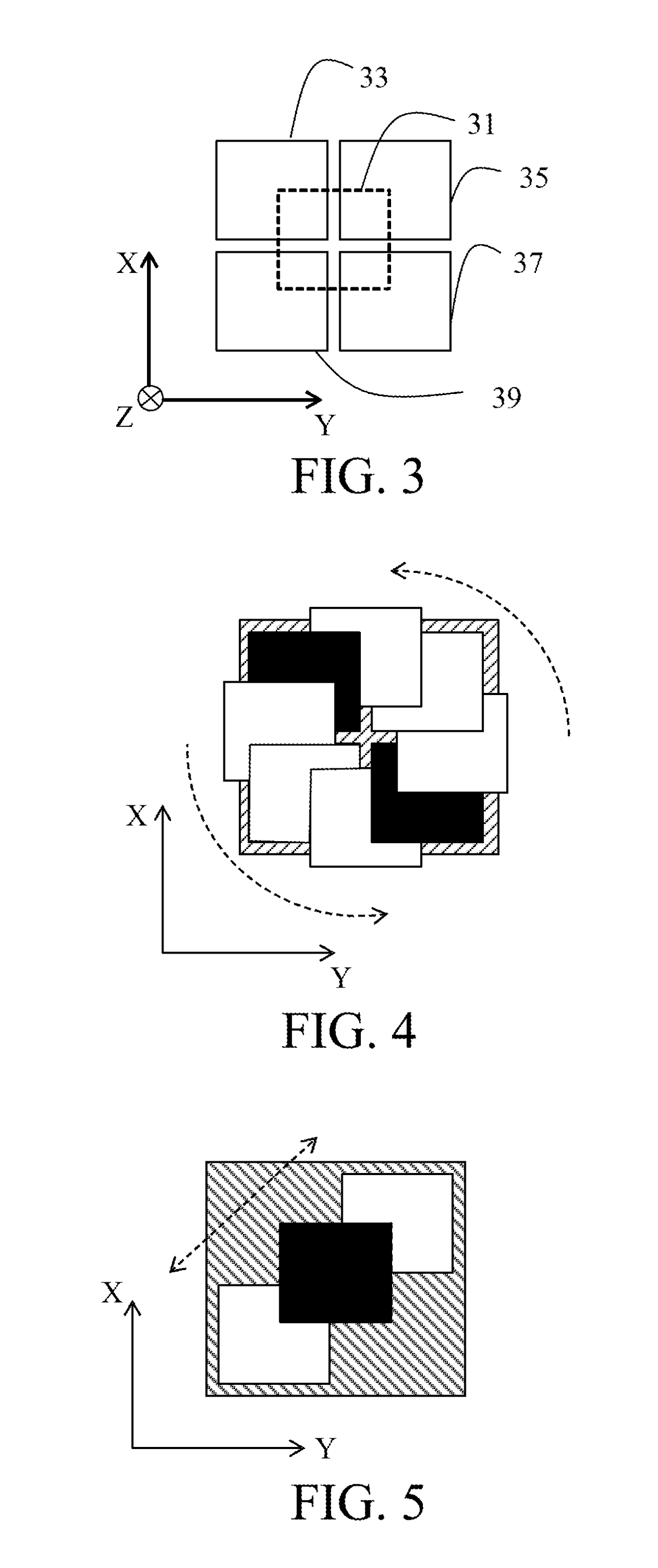
[0047]Thereby, as illustrated in FIG. 4, the glass plate is rotated so that one projection pixel draws a circle on the projection surface. The resolution may lower due to an overlapping area between the projection pixels corresponding to two image signals as illustrated by a black square (referred to as a “different image overlap area” hereinafter).
[0048]While the resolution can be enhanced in the direction that connects the upper right to the lower left in FIG. 4 by rotating the glass plate around the optical axis, the resolution is l...
PUM
 Abstract
Description
Claims
Application Information
 - R&D
- Intellectual Property
- Life Sciences
- Materials
- Tech Scout
- Unparalleled Data Quality
- Higher Quality Content
- 60% Fewer Hallucinations
Browse by: Latest US Patents, China's latest patents, Technical Efficacy Thesaurus, Application Domain, Technology Topic, Popular Technical Reports.
© 2025 PatSnap. All rights reserved.Legal|Privacy policy|Modern Slavery Act Transparency Statement|Sitemap|About US| Contact US: help@patsnap.com


