Electrophysiology catheter

a catheter and electrophysiology technology, applied in the field of electrophysiology catheters, can solve the problems of increased safety risk, perforation of tissue, and inability to effectively block aberrant electrical signals or nerve conduction, and achieve the effects of improving the contact force measurement accuracy of the catheter distal portion, ensuring safety, and ensuring accuracy

Active Publication Date: 2019-10-10
SHANGHAI MICROPORT EP MEDTECH CO LTD
View PDF6 Cites 7 Cited by
  • Summary
  • Abstract
  • Description
  • Claims
  • Application Information

AI Technical Summary

Benefits of technology

[0026]In summary, compared to the design with the strain sensors overlapping the hollow portion, arranging them over solid portions of the elastic tube in the electrophysiology catheter of the present invention allows the strain gauges to collect more accurate electrical signals and thus improve contact force measurement accuracy of the catheter distal portion.
[0027]In particular, disposing the strain gauges between opposing ends of the arcuate first through-slots or between adjacent spiral third through-slots or between adjacent axially-extending fourth through-slots in accordance with the present invention enables the strain gauges to collect higher-quality electrical signals. Moreover, the spiral third through-slots impart higher circumferential uniformity to the elastic tube, helping in collecting more accurate electrical signals.
[0028]In more particular, the axially-extending second through-slots provided at the ends of the first through-slots in accordance with the present invention can further lower the rigidity of the elastic tube, thereby increasing the deformability of the elastic tube, helping in enhancing the electrical signals collected by the strain gauges and making the measurement results more accurate.
[0029]Further, the force sensor according to the present invention is less bulky, more sensitive, less affected by magnetic fields, immune from temperature variations and cost-effective. Furthermore, in addition to the magnitude of a contact force exerted by the surface of a vessel wall or organ on the catheter distal portion, the plurality of strain gauges can also measure axial and lateral components of the force and an associated contact angle as well. This can provide the physician with valuable additional information based on which better surgical outcomes can be obtained.

Problems solved by technology

Weak contact will lead to a shallow lesion incapable of allowing effective blockage of the aberrant electrical signals or nerve conduction.
However, excessively strong contact may probably lead to perforation of the tissue, which causes an increased safety risk.
However, such sensors suffer from certain limitations in practical use, such as tending to give distorted results due to interference from external magnetic fields and limiting other catheter functionalities such as three-dimensional magnetic positioning due to the use of magnetic fields.
Although such systems are good at axial load measurement, they are lack of accuracy in non-axial load measurement.
There are still other catheters employing fiber-optic systems for sensing contact forces with the vessel wall or organ, but they are difficult to package and make and expensive and require external electrical signal devices.

Method used


Image

  • Electrophysiology catheter
  • Electrophysiology catheter
  • Electrophysiology catheter

Examples


embodiment 1

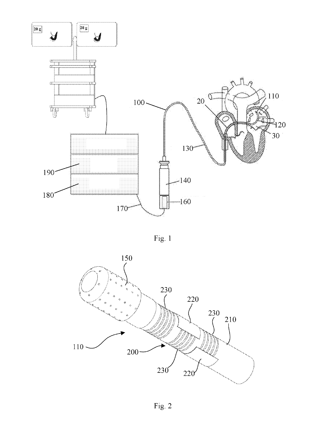
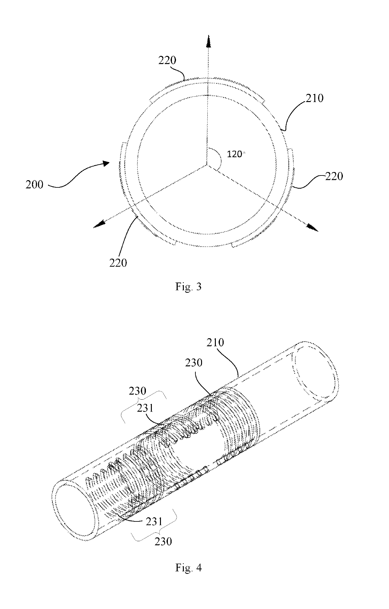
[0050]FIG. 1 is a schematic illustrating cardiac ablation carried out with an ablation catheter according to Embodiment 1 of the present invention. FIG. 2 is a structural schematic of a distal portion of the ablation catheter according to Embodiment 1 of the present invention.

[0051]Referring to FIGS. 1 and 2, the ablation catheter 100 include, sequentially connected, the catheter distal portion 110, a deflectable section 120, a main body 130 and a control handle 140. The catheter distal portion 110 is equipped with an ablation electrode 150 intended to be brought into contact with a vessel wall or tissue and apply energy thereto for ablation. However, the catheter distal portion 110 is not limited to be equipped with the ablation electrode 150, since a mapping electrode may be alternatively equipped thereon. In application, the ablation catheter 100 will be inserted through a percutaneous sheath 20 and the inferior vena cava into the left atrium 30 to perform ablation there.

[0052]Fo...

embodiment 2

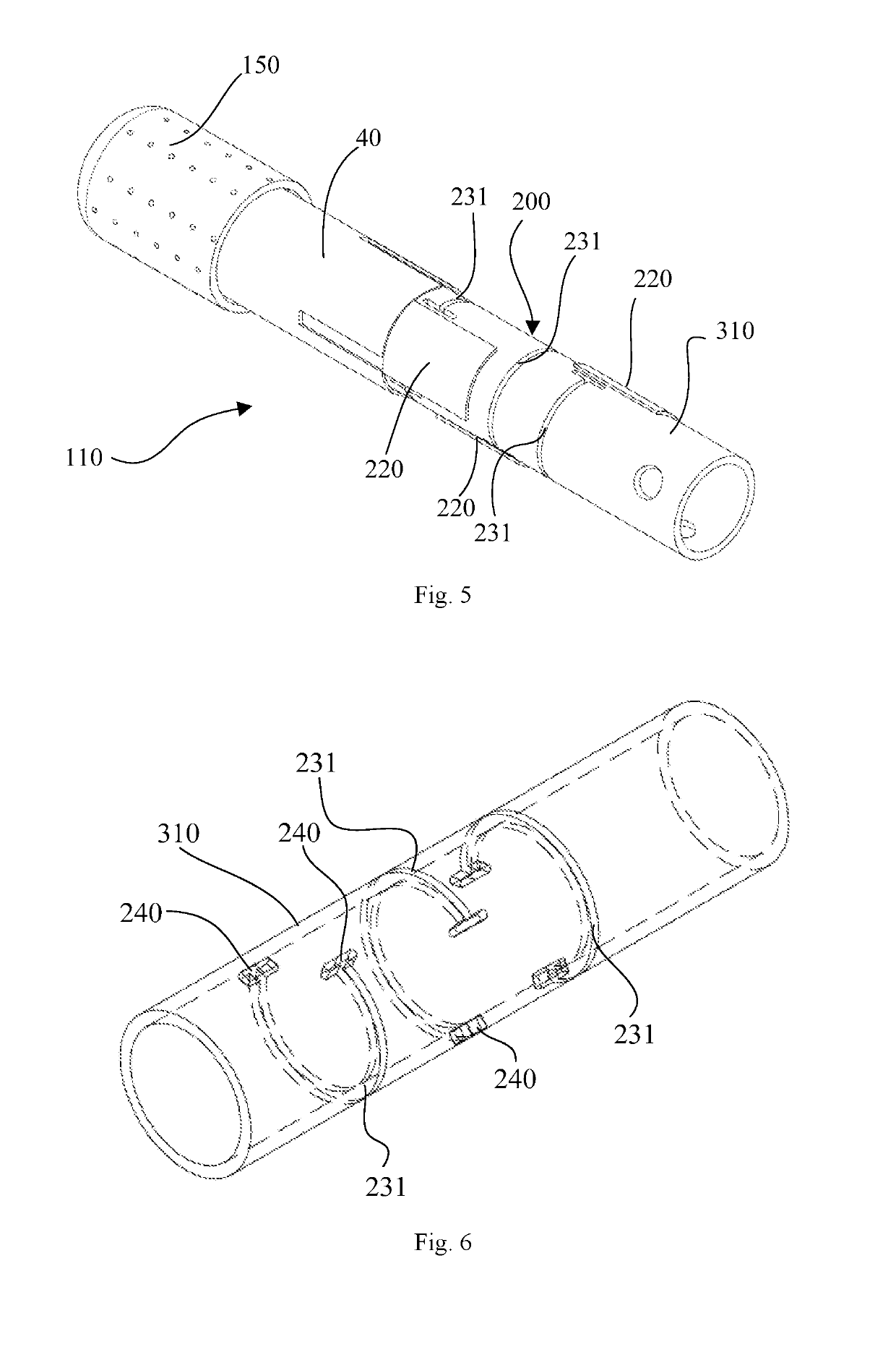
[0070]FIG. 5 shows a structural schematic of a distal portion of an ablation catheter according to Embodiment 2 of the present invention, and FIG. 6 is a structural schematic of an elastic tube according to Embodiment 2 of the invention. In the following description, a width of a first through-slot 231 is defined as a length that the first through-slot spans along the axial direction of the elastic tube, while a length of the first through-slot 231 is defined as a length the first through-slot 231 extends along the circumferential direction of the elastic tube.

[0071]In this Embodiment, the elastic tube 310 also has a hollow portion including arcuate first through-slots 231. Specifically, they may be arcuate slots cut in a single circumferential section of the outer surface of the elastic tube 310. Preferably, the length of each of the first through-slots 231 is two-thirds to four-fifths of the circumference of the elastic tube 310. The first through-slots 231 impart increased elasti...

embodiment 3

[0080]FIG. 8 is a structural schematic of an elastic tube with spiral through-slots according to Embodiment 3 of the present invention, and FIG. 9 schematically illustrates how strain gauges are distributed on the elastic tube according to Embodiment 3 of the present invention.

[0081]As shown in FIGS. 8 to 9, there is / are spiral third through-slot(s) 420 cut in the outer surface of the elastic tube 410. The number of the spiral through-slot(s) may be one, two or more than two. The greater the number of the third through-slot(s) 420 is, the higher the circumferential uniformity of the elastic tube 410 and the lower the elastic modulus thereof will be. In practice, the number of the spiral through-slot(s) may be properly selected according to a strain measurement range of the strain gauges 430. Preferably, when three strain gauges 430 are used, three third through-slots 420 are formed, so that each of the strain gauges 430 is disposed between corresponding two of the third through-slot...


PUM


Abstract

An electrophysiology catheter (100) includes a catheter distal portion (110) on which a force sensor (200) is arranged. The force sensor (200) includes an elastic tube (210) and strain gauges (220). The elastic tube (210) has a hollow portion in its wall, and the strain gauges (220) are disposed external to the hollow portion. Compared to the design with the strain gauges (220) overlapping the hollow portion, arranging them over solid portions of the elastic tube (210) allows the strain gauges (220) to collect more accurate electrical signals while suffering from less interference. This can result in a significant improvement in contact force measurement accuracy of the catheter distal portion (110).

Description

TECHNICAL FIELD[0001]The present invention relates to the field of medical devices and, in particular, to an electrophysiology catheter.BACKGROUND[0002]In recent years, catheter systems have been developed for interventional treatment of, for example, cardiac arrhythmias and refractory hypertension. For example, in the treatment of atrial fibrillation, one type of cardiac arrhythmia, an ablation or mapping catheter may be introduced into the heart via a vein or artery to find an aberrant electrical signal trigger or pathway by endocardial mapping, and then apply energy to the trigger or pathway to ablate it to eliminate or alter undesirable electrical signals, thus achieving curative results. Another example is the treatment of refractory hypertension through renal artery ablation, in which an ablation catheter may be arterially introduced into an artery connecting the abdominal aorta and the kidney to ablate and block the parasympathetic nerve pathway to lower the blood pressure.[0...

Claims


Application Information

Patent Timeline
Patent Type & Authority Applications(United States)
IPC IPC(8): A61B18/14A61B5/042
CPCA61B5/6852A61B5/0422A61B2018/1435A61M25/0141A61B2018/00577A61B2562/0266A61M2025/0002A61B18/1492A61B5/6885A61B18/12A61B18/14A61B2018/00345A61B2018/00636A61B2562/0247A61B2562/0261A61B2562/06A61B5/24A61B2018/00773G01L1/2262G01L1/2287G01B7/18G01B5/30A61B5/287
Inventor SHEN, LEIWANG, HUIMIAO, TAOLIANG, BOTAN, JIAHONG
Owner SHANGHAI MICROPORT EP MEDTECH CO LTD
Why Eureka
Try Eureka