
Actuator and robot

Active Publication Date: 2009-07-09
HONDA MOTOR CO LTD
View PDF2 Cites 6 Cited by
  • Summary
  • Abstract
  • Description
  • Claims
  • Application Information

AI Technical Summary

Benefits of technology

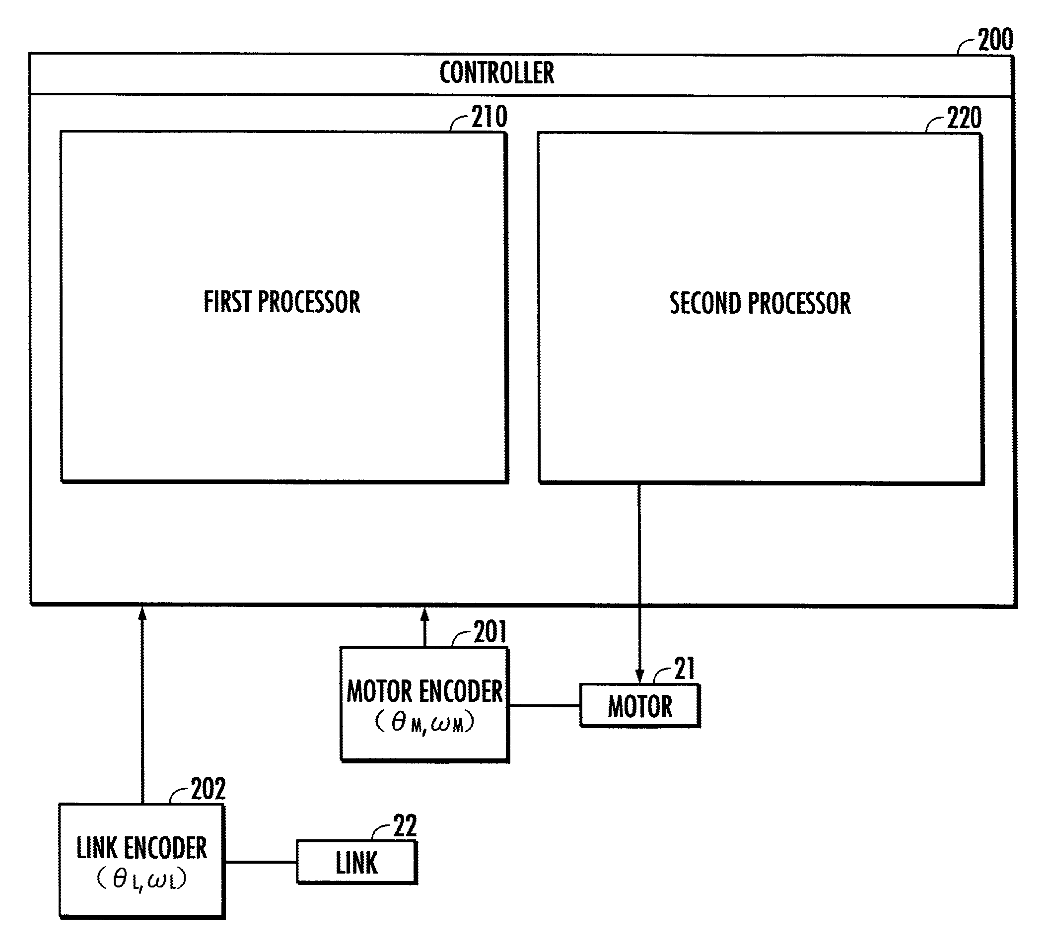
[0009]An object of the present invention therefore is to provide an actuator and a robot which are capable of properly adjusting the compliance of the motions of links in response to external forces according to an environment or application.

Problems solved by technology

However, according to the first technique, improving the compliance requires prompt responses of the arm to the command.
In particular, there is a restriction that the rigidity of the arm cannot be reduced because of the need for securing prompt motions of the arm in response to commands, thus making it difficult to achieve a lighter-weight, compact arm and to eventually achieve a multifunctional arm.
This results in deteriorated allowances of phases and gains, making it difficult to fully exercise damping effect.

Method used


Image

  • Actuator and robot
  • Actuator and robot
  • Actuator and robot

Examples


Embodiment Construction

[0032]Embodiments of an actuator and a robot in accordance with the present invention will be described with reference to the accompanying drawings. The constructions of a robot and an actuator as the embodiments of the present invention will be described.

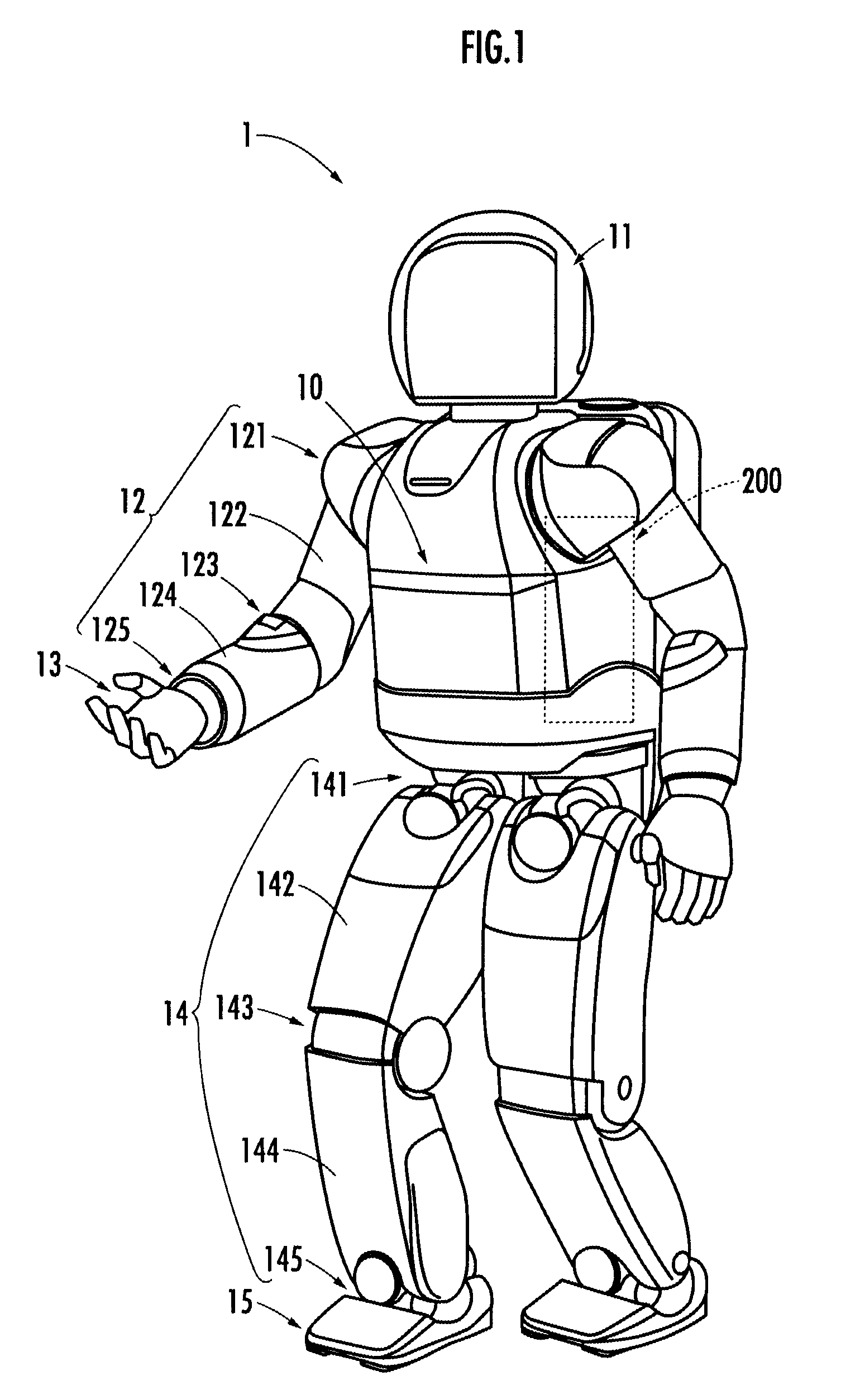
[0033]A robot 1 illustrated in FIG. 1 is a humanoid robot having a body 10, a head 11 disposed on the top of the body 10, right and left arms 12 provided at an upper portion of the body 10 such that they extend from both sides of the upper portion, hands 13 provided at the distal ends of the right and left arms 12, right and left legs 14 extendedly provided downward from the bottom of the body 10, and feet 15 provided at the distal ends of the right and left legs 14.

[0034]The body 10 is constructed of an upper section and a lower section vertically connected such that they may relatively rotate about a yaw axis. The head 11 is capable of making a motion, such as moving about the yaw axis, with respect to the body 10.

[0035]Each of t...


PUM


Abstract

An actuator and a robot are capable of properly adjusting the compliance of the motions of links in response to external forces according to an environment or application. The actuator sets a drive command angular velocity on the basis of a desired motor angular velocity, which is the resultant angular velocity of a desired link angular velocity and a desired driven angular velocity. The component of the desired link angular velocity included in a resultant desired velocity imparts stiffness to the motion of a link, while the component of the desired driven angular velocity included in the resultant desired velocity imparts flexibility to the motion of the link. Thus, the balance between the stiffness and the flexibility of the motion of the link is adjusted by adjusting the resultant ratio between the desired link angular velocity and the desired driven angular velocity.

Description

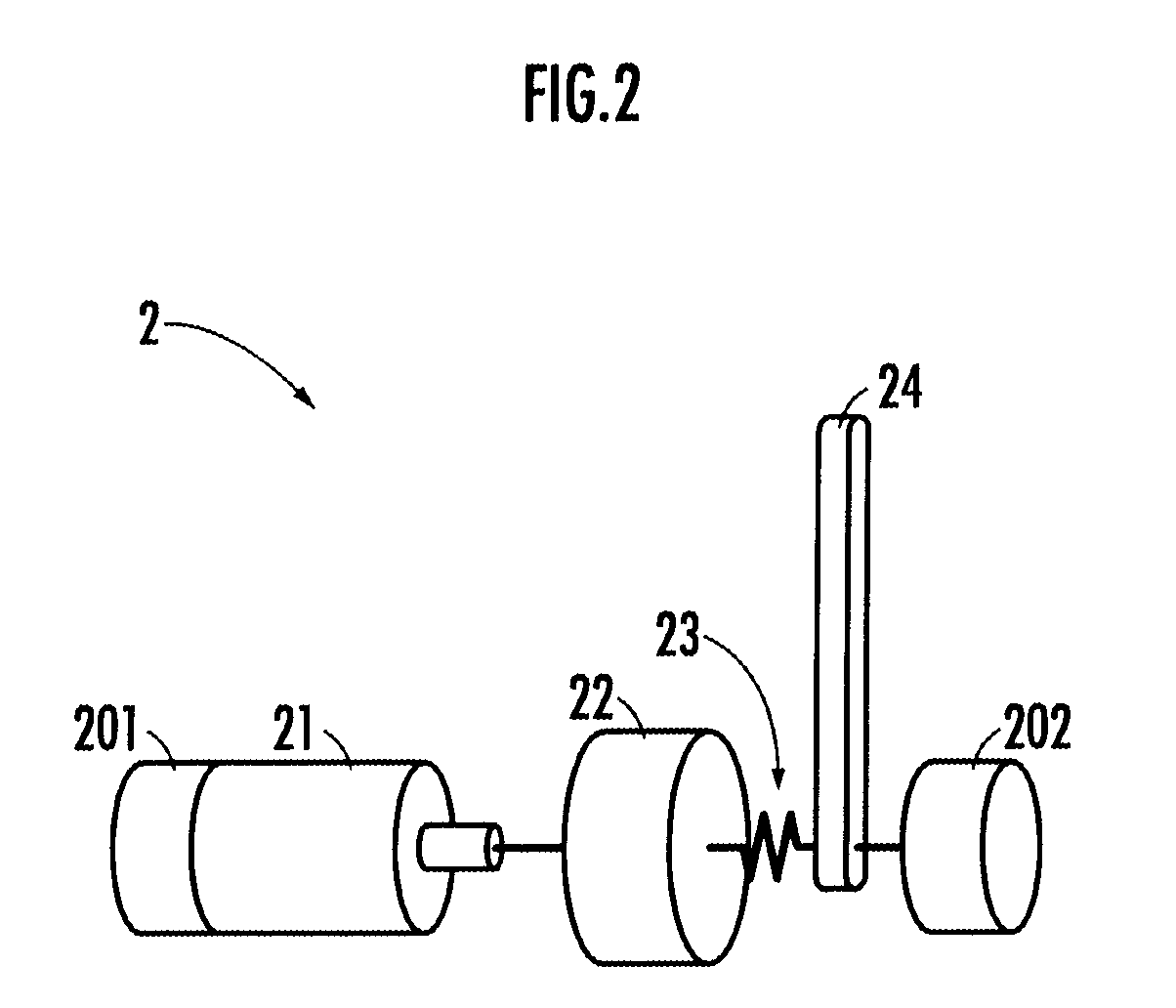
BACKGROUND OF THE INVENTION[0001]1. Field of the Invention[0002]The present invention relates to an actuator equipped with a drive mechanism, a flexible element interposed between an output shaft of the drive mechanism and a load, and a controller which controls an output to be applied to the load from the drive mechanism through the intermediary of the flexible element by controlling the operation of the drive mechanism, and a robot.[0003]2. Description of the Related Art[0004]There are the following two techniques, as engineering practices, for imparting compliance or flexibility to an arm of a robot so as to protect the arm or a component thereof from damage if the arm is subjected to an external force.[0005]According to a first technique, an external force applied to the arm is measured on the basis of an output signal from an external force sensor provided in the arm, and a measurement result is input to a compliance model to obtain an output. Based on a command obtained as the...

Claims


Application Information

Patent Timeline
IPC IPC(8): G05B15/00
CPCB25J9/1633G05B2219/40264G05B2219/39183
Inventor UEBAYASHI, YUICHI
Owner HONDA MOTOR CO LTD
Learn More