Vehicle sunshade assembly

a technology for sunshade and vehicles, applied in the field of sunshade, can solve the problems of assembly and manufacture of sunshade b>1

Inactive Publication Date: 2009-07-16
MACAUTO IND CO LTD
View PDF12 Cites 55 Cited by
  • Summary
  • Abstract
  • Description
  • Claims
  • Application Information

AI Technical Summary

Problems solved by technology

However, such a design of mounting a plurality of the ball-shaped members 14 to the screen 13 makes assembly and manufacture of the sunshade 1 difficult...

Method used


Image

  • Vehicle sunshade assembly
  • Vehicle sunshade assembly
  • Vehicle sunshade assembly

Examples


Embodiment Construction

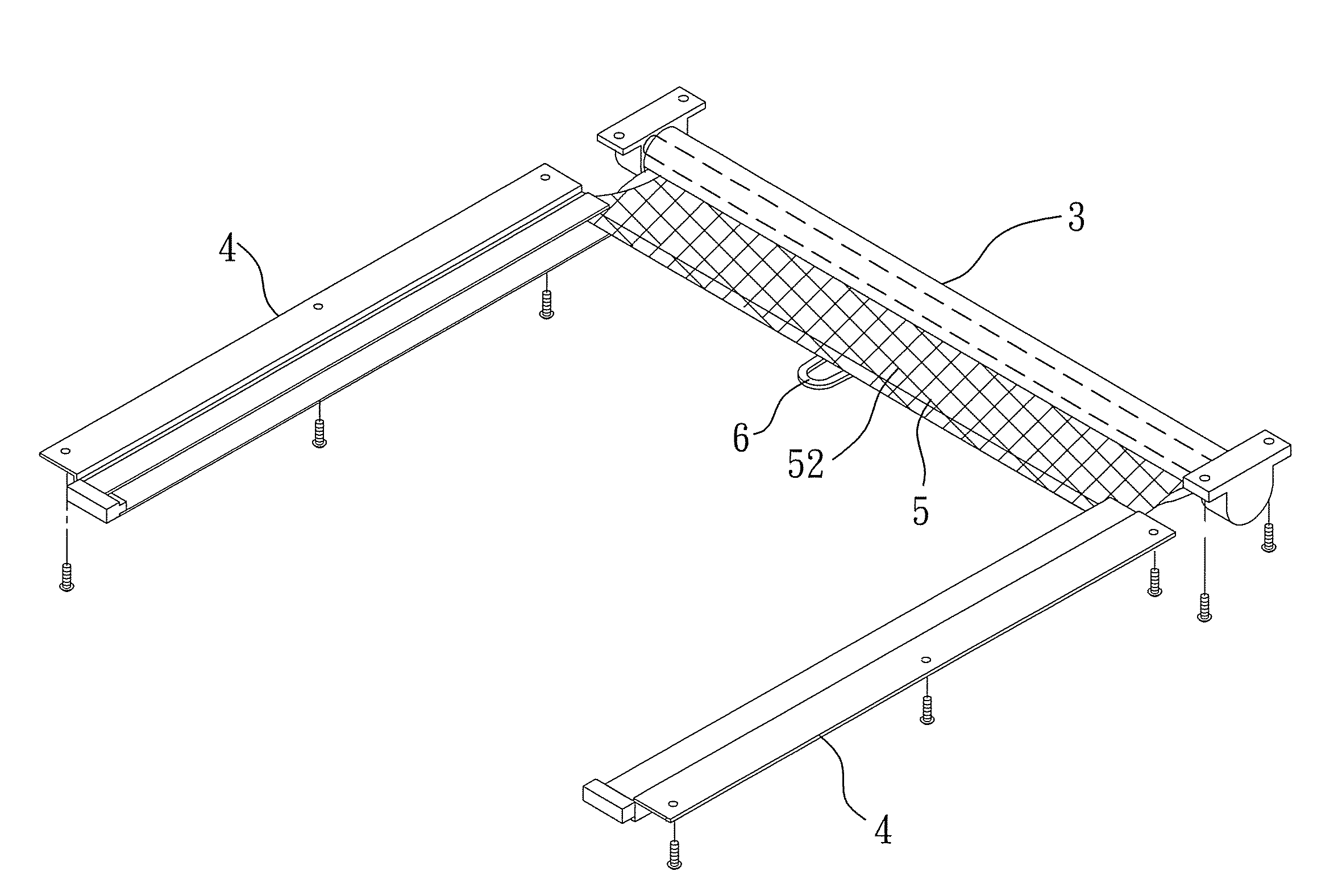
[0016]As shown in FIGS. 4, 5, and 6, the preferred embodiment of a sunshade assembly of the present invention is adapted to be assembled on a sunroof 900 of a vehicle 9 to thereby selectively cover the sunroof 900.

[0017]The sunshade assembly includes a roller 3, a pair of rails 4, a screen unit 5, and a loop 6. The roller 3 is continuously biased to rotate in a winding direction. Since the construction of the roller 3 is known to those skilled in the art and is not the primary feature of the present invention, a detailed description of the same will be dispensed with herein for the sake of brevity.

[0018]With additional reference to FIG. 7, each rail 4 includes an upper wall 42, and a lower wall 43 cooperating with the upper wall 42 to define a recess 40 and an opening 401 therebetween. The opening 401 is in spatial communication with the recess 40 and faces the other of the rails 4.

[0019]The screen unit 5 includes a screen 52 and a pair of abutment pieces 51. The screen 52 has oppos...


PUM


Abstract

A sunshade assembly includes a roller, a pair of rails, and a screen unit. Each rail includes an upper wall, and a lower wall cooperating with the upper wall to define a recess therebetween. A screen unit includes a screen having opposite peripheral edge portions and operable between a wound state and an extended state, and a pair of abutment pieces. Each abutment piece is slidably disposed in the recess, and includes an arcuate first portion fixed to a respective one of the peripheral edge portions of the screen and abutting against the lower wall of the respective rail, and a second portion. The first portion arches downwardly in a normal state, and arches upwardly in an abnormal state caused by pulling of the screen. The second portion abuts against the lower wall in the normal state and against the upper wall in the abnormal state.

Description

BACKGROUND OF THE INVENTION[0001]1. Field of the Invention[0002]The invention relates to a sunshade, more particularly to a sunshade assembly for vehicles.[0003]2. Description of the Related Art[0004]As illustrated in FIG. 1, a conventional vehicle sunshade 1 that may be assembled to a vehicle sunroof (not shown) comprises a retracting unit 11, a pair of rails 12, and a screen 13 that is operable between a wound state, where the screen 13 is wound on the retracting unit 11, and an extended state, where the screen 13 is advanced along the pair of rails 12. In order to prevent the screen 13 from being removed from the rails 12 as a result of sudden and excessive wind forces entering through the sunroof or by being struck by a person in the vehicle, a plurality of ball-shaped members 14 are fixed to the opposite lateral edges of the screen 13. Through design of the ball-shaped members 14 such that they are larger than slide openings 120 in the rails 12, the screen 13 is prevented from ...

Claims


Application Information

Patent Timeline
IPC IPC(8): B60J1/20B60J3/00
CPCB60J7/0015
Inventor LIN, PAUL
Owner MACAUTO IND CO LTD
Why Eureka
Try Eureka