

Tire building method and rubber strip bonding apparatus
a technology of rubber strip and building method, which is applied in the direction of tyres, domestic applications, other domestic articles, etc., can solve the problems of shortening the pressing force, voids are produced, and fore portions in the advancing direction of traverse movement are not pressed sufficiently
- Summary
- Abstract
- Description
- Claims
- Application Information
AI Technical Summary
Benefits of technology
Problems solved by technology
Method used
Image

Examples
Embodiment Construction
[0021]A mode for carrying out the invention will be described below on the basis of an embodiment shown in the drawings.
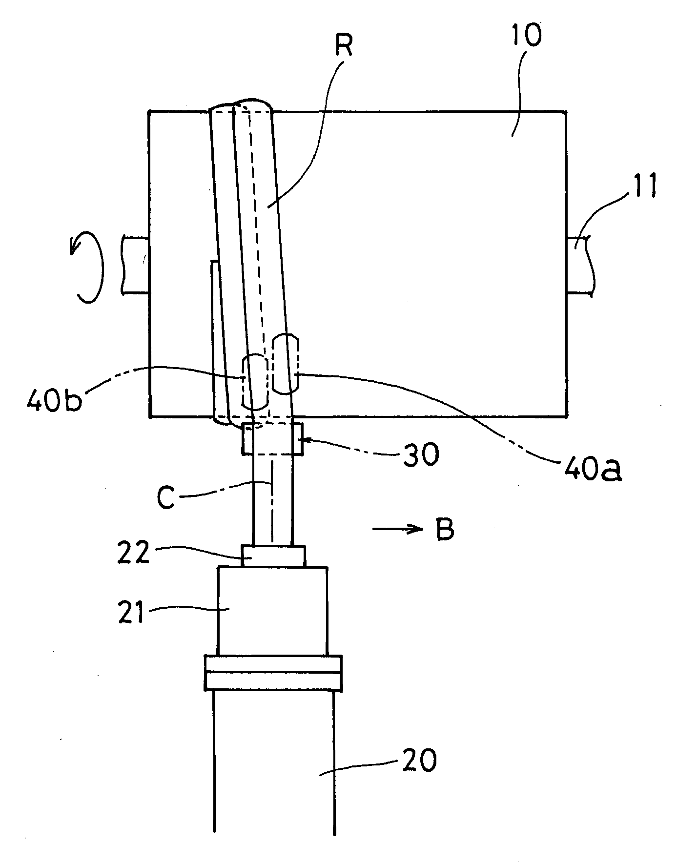
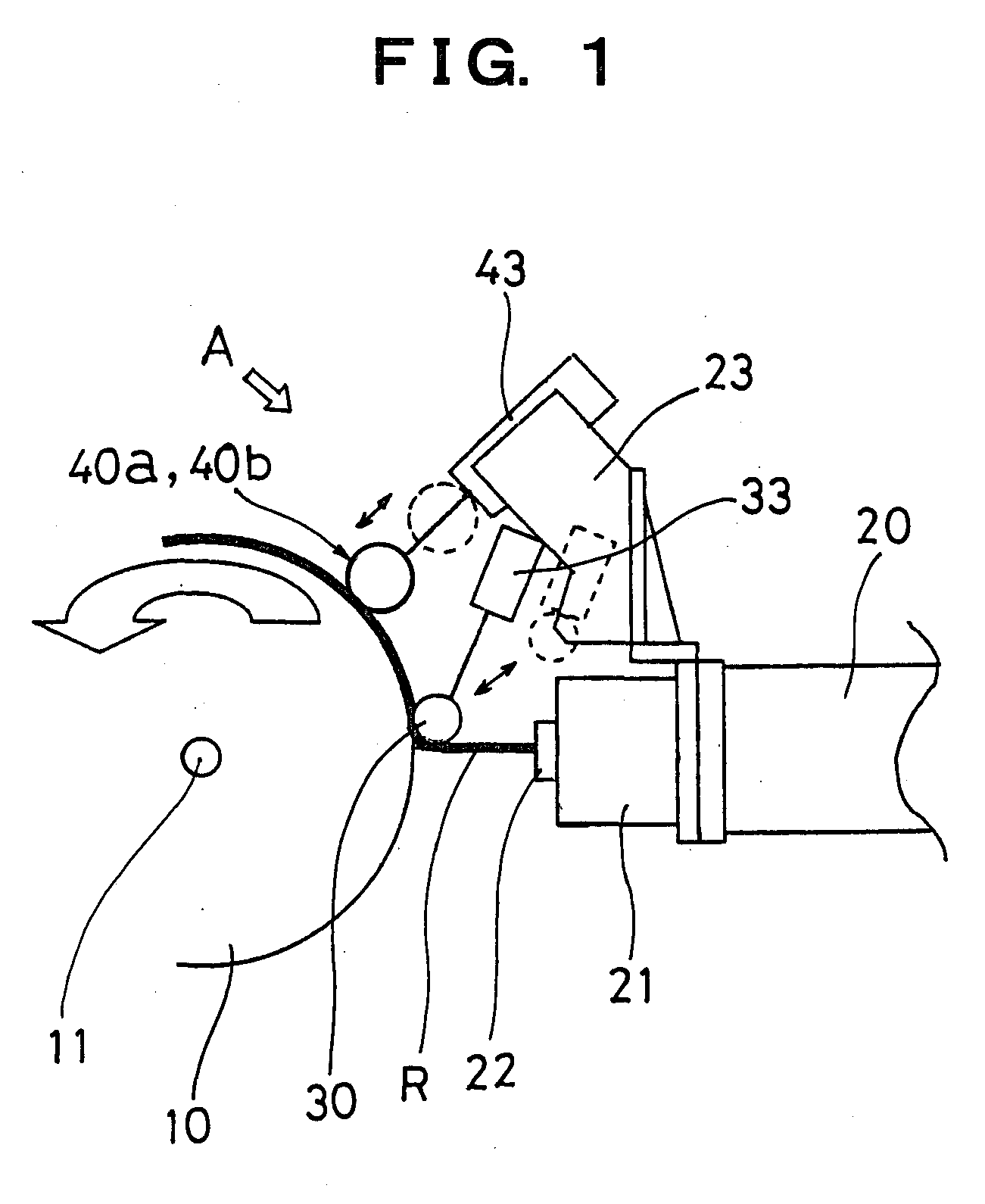
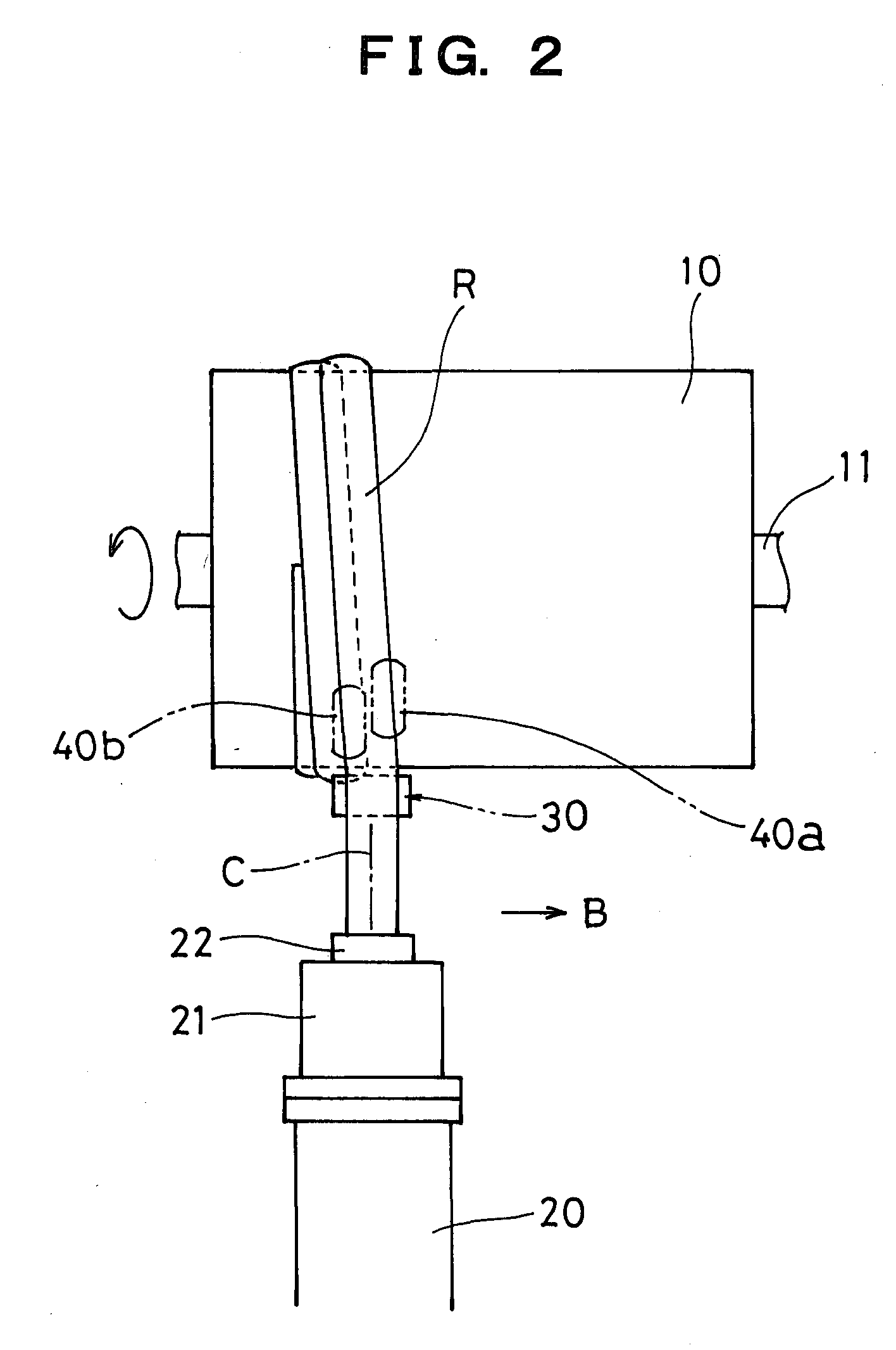
[0022]FIG. 1 is a schematic, side view showing a state, in which a ribbon-shaped rubber strip is wound by a building apparatus, which carries out a tire building method according to the invention, FIG. 2 is a schematic, plan view showing the state, FIG. 3 is a schematic, plan view showing a state of press by a holding roll as viewed in a direction of an arrow A in FIG. 1, FIGS. 4 and 5, respectively, are schematic, plan views showing a state of press by a stitching roll as viewed in the direction of the arrow A in FIG. 1, FIG. 6 is a cross sectional view showing a posture of winding of rubber strips, and FIG. 7 is a view illustrating a pressed state by a conventional holding roll.
[0023]In the drawings, the reference numeral 10 denotes a rotary support body for building, which is rotatable about a central axis 11, the rotary support body comprising a cylindrical-sha...
PUM
| Property | Measurement | Unit |
|---|---|---|
| Width | aaaaa | aaaaa |
Abstract
Description
Claims
Application Information