

Faucet apparatus
a technology of faucet and faucet body, which is applied in the direction of electric generator control, renewable energy generation, greenhouse gas reduction, etc., can solve the problems of fear of controller submergedness and complicated assembly steps, and achieve the effect of improving the arrangement relationships of incorporated components
- Summary
- Abstract
- Description
- Claims
- Application Information
AI Technical Summary
Benefits of technology
Problems solved by technology
Method used
Image

Examples
first embodiment
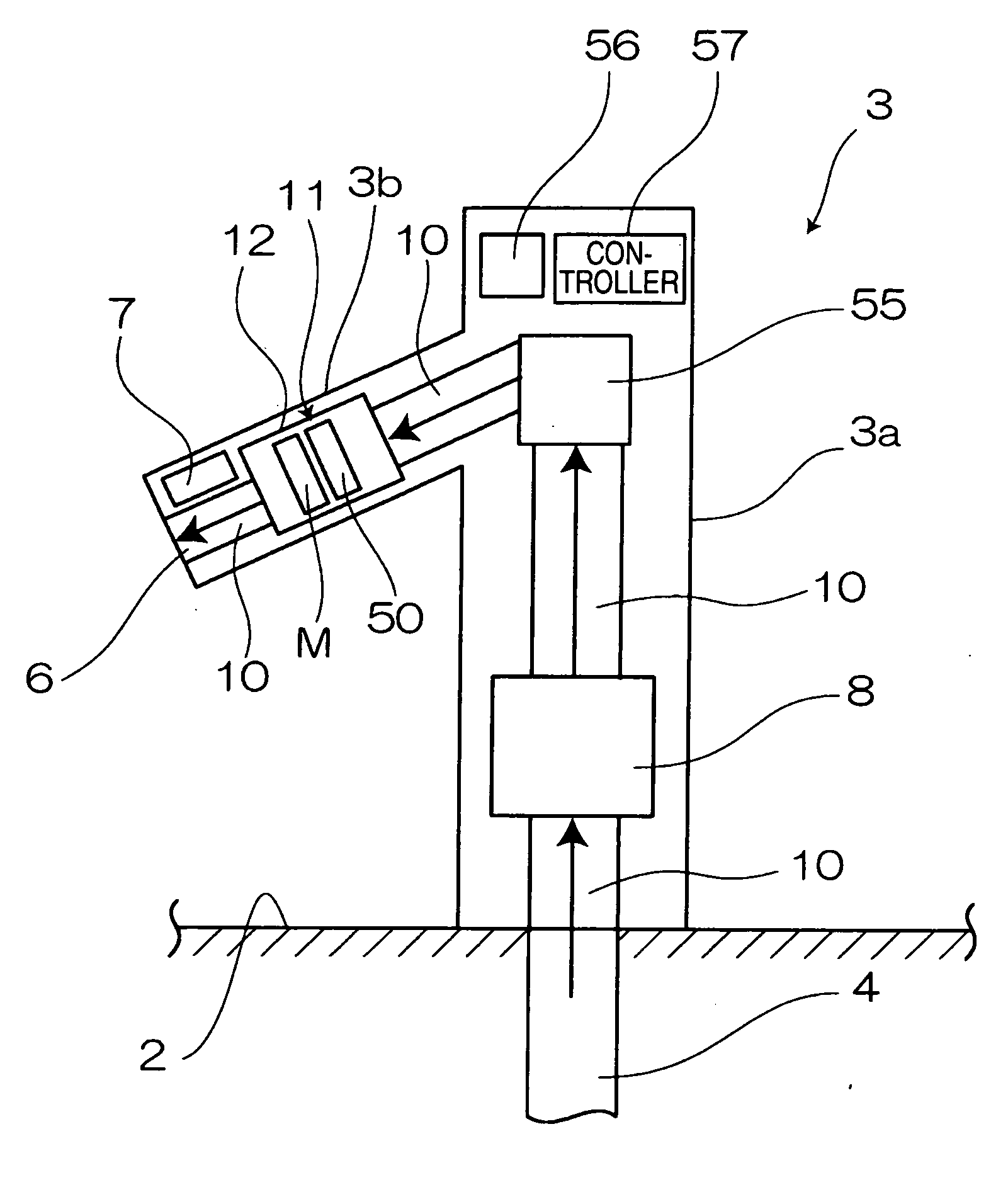
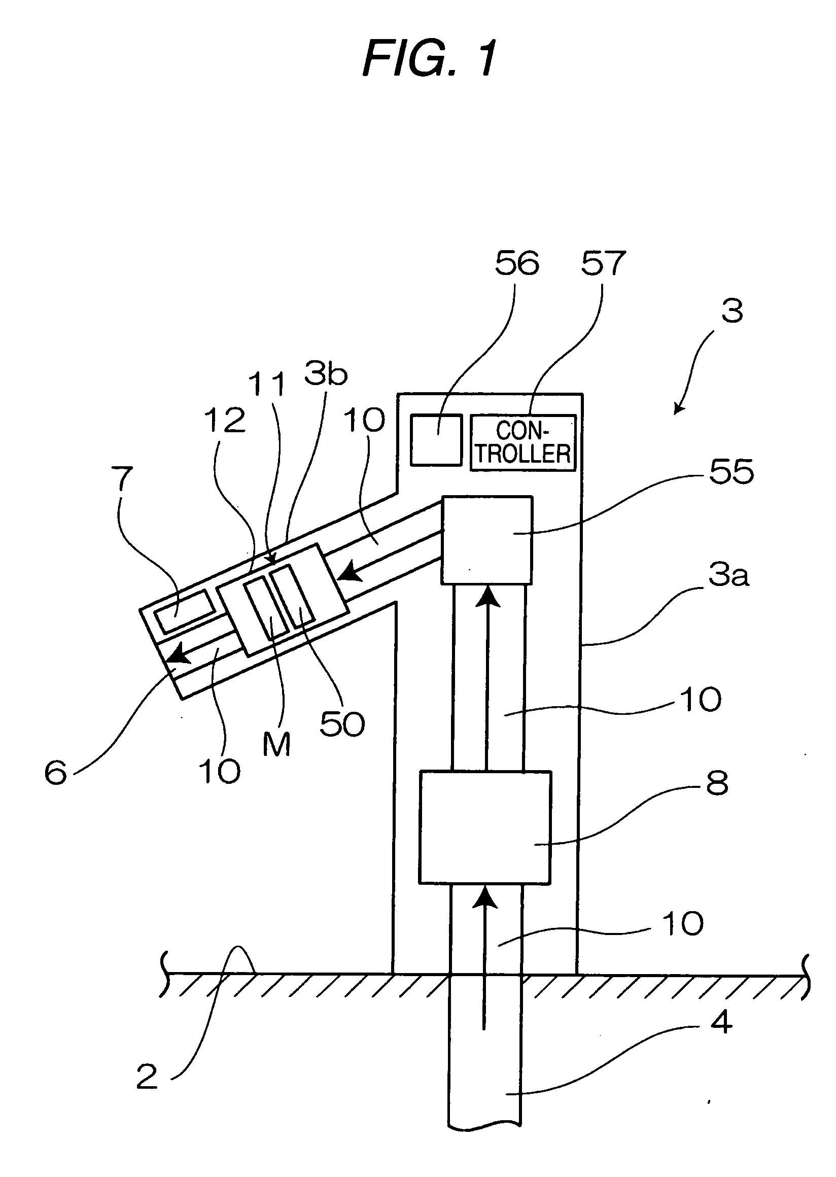
[0024]FIG. 1 is a schematic view showing the internal configuration of a faucet apparatus 3 of a
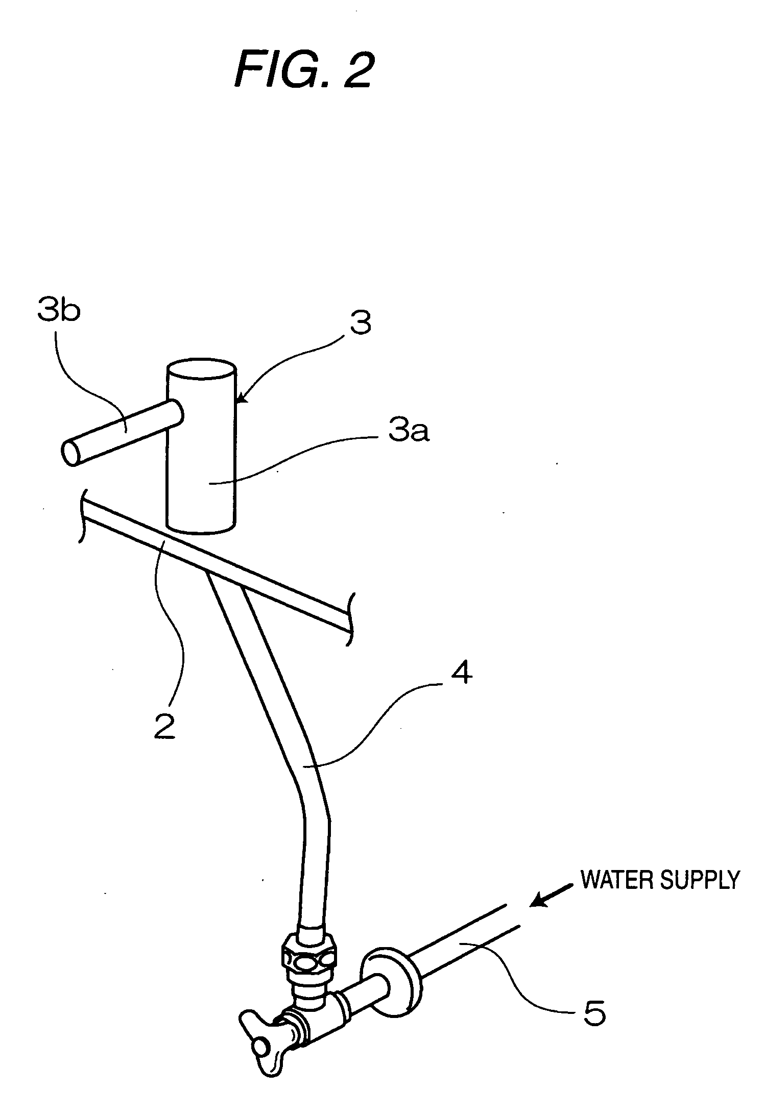
[0025]FIG. 2 is a schematic view showing an appearance of the faucet apparatus of the first embodiment and an example of mounting.
[0026]The faucet apparatus 3 of the first embodiment is mounted in, for example, a washstand 2. The faucet apparatus 3 is connected to a water inflow port 5 for tap water or the like, through a piping 4. The faucet apparatus 3 has a cylindrical body 3a, and a water discharger 3b. The water discharger 3b is disposed in an upper portion of the body 3a while extending in a radially outward direction of the body 3a. A water discharging port 6 is formed at the tip end of the water discharger 3b, and a sensor 7 is incorporated in the vicinity of the water discharging port 6.
[0027]A water supply channel 10 which guides water that inflows from the water inflow port 5 and flows through the piping 4, to the water discharging port 6 is formed inside the faucet apparatus 3...
second embodiment
[0063]FIG. 9 is a schematic view showing the internal configuration of a faucet apparatus of a
[0064]The faucet apparatus of the second embodiment is different in design of the case body from the above-described first embodiment. Unlike the first embodiment, the body and the water discharger are not distinctly distinguished from each other, and a water discharging port 41 is directly disposed on the curved body 60. In the body 60, a water supply channel 40 is disposed, and the solenoid valve 8, the constant flow valve 55, and the generator 11 are disposed in the sequence starting from the upstream side of the water supply channel 40.
[0065]Also in the second embodiment, the coil 50 and the controller 57 are placed on the same side with respect to the magnet M (in the embodiment, for example, on the side of the downstream end face of the magnet M). Therefore, the wiring for taking out the output of the coil 50 is not required to be laid to the controller 57, beyond the magnet M, and th...
PUM
 Abstract
Description
Claims
Application Information