
Image forming apparatus

a technology of forming apparatus and forming plate, which is applied in the direction of digital output to print units, digitally marking record carriers, instruments, etc., can solve the problems of difficult to specify which functional setting, incompatible with any of the original functional settings, etc., and achieve the effect of facilitating the execution of incompatible combinations

Inactive Publication Date: 2009-07-30
KYOCERA DOCUMENT SOLUTIONS INC
View PDF2 Cites 12 Cited by
  • Summary
  • Abstract
  • Description
  • Claims
  • Application Information

AI Technical Summary

Benefits of technology

The present invention relates to an image forming apparatus that can display and change settings for various functions of image formation. The apparatus includes a setting section and a setting display section that can display options for each function. The apparatus also includes a determination section and a change section that can determine if a combination of options from different functions is incompatible and change the display form of the option accordingly. This allows users to easily identify and change the function responsible for an incompatible combination. The technical effect of the invention is to clearly and quickly display the function responsible for an incompatible combination, making it easier for users to change the settings and cancel the incompatibility.

Problems solved by technology

.” Even when a user tries to change a part of a group of functional settings, the intended functional change may be incompatible with any of the original functional settings.
In this case, it has been difficult to specify which functional setting is the cause of the incompatible combination.

Method used


Image

  • Image forming apparatus
  • Image forming apparatus
  • Image forming apparatus

Examples


Embodiment Construction

[0028]Selected embodiments of the present invention will now be explained with reference to the drawings. It will be apparent to those skilled in the art from this disclosure that the following descriptions of the embodiments of the present invention are provided for illustration only and not for the purpose of limiting the invention as defined by the appended claims and their equivalents.

[0029]In the embodiment, the present invention is realized as a digital multifunction peripheral (digital MFP, an embodiment of an image forming apparatus).

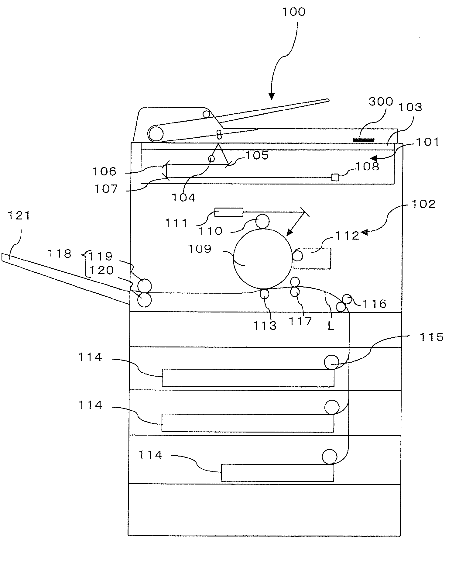
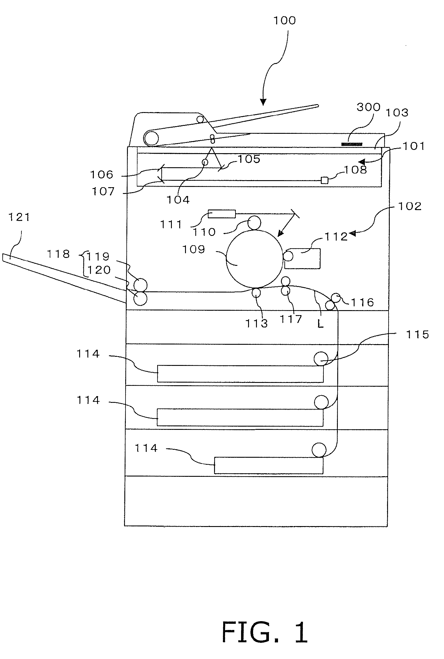
[0030]FIG. 1 is a view of a schematic diagram illustrating an entire configuration of a MFP 100 according to a preferred embodiment of the present invention. When a user makes a photocopy using the MFP 100, the user puts a manuscript on a platen 103. Then, the user inputs a copy instruction by operating an operating button. The operating button is provided on a touch panel 300 disposed in the vicinity of the platen 103. When the copy instruction...


PUM


Abstract

An image forming apparatus includes a setting section, a setting display section, a determination section, a change section, and an incompatible option display section. The setting section sets image formation functions, which include first and second functions. The setting display section displays a single or plurality of options on each of setting screens. The single or plurality of options is set as a setting condition for each function. The setting screens respectively correspond to the functions. The determination section determines if a combination of options is incompatible. The change section changes a display form of the option of the first function when the determination section determines that the combination is incompatible. The incompatible option display section displays a setting screen of the option of the second function when the option of the first function is selected after the display form of the option of the first function is changed.

Description

CROSS-REFERENCE TO RELATED APPLICATIONS[0001]This application claims priority under 35 U.S.C. §119 to Japanese Patent Application No. 2008-015627 filed on Jan. 25, 2008. The entire disclosure of Japanese Patent Application No. 2008-015627 is hereby incorporated herein by reference.BACKGROUND OF THE INVENTIONField of the Invention[0002]The present invention relates to an image forming apparatus such as a printer, a copier, and a multifunction peripheral (MFP).[0003]Recently, image forming apparatuses (e.g., a copier and a MFP) have become indispensable office machines in working environments (e.g., an office in a company). Meanwhile, image forming apparatuses have been recently widely used at home. Their functions have been increasingly diversified. For example, a copier is configured to be capable of realizing a variety of functions. The variety of functions include selection of printing paper, selection of a paper feeding tray, zoom-in / out printing, color printing, duplex printing,...

Claims


Application Information

Patent Timeline
Patent Type & Authority Applications(United States)
IPC IPC(8): G06F3/12
CPCG03G2215/00869H04N1/00411H04N1/00413G03G15/502H04N1/0048H04N1/00482H04N2201/0094H04N1/00432
Inventor NAKANISHI, SHINICHI
Owner KYOCERA DOCUMENT SOLUTIONS INC
Learn More