Night sight and method of making the same

a technology of night sights and focusing assemblies, applied in the direction of instruments, optical elements, electromagnetic radiation sensing, etc., can solve the problems of decreasing the sensitivity of the focusing assembly to tilt, rotation, or decentration, and achieve the effect of resisting parallax and resisting parallax

Active Publication Date: 2009-08-06
FLIR SURVEILLANCE
View PDF22 Cites 16 Cited by
  • Summary
  • Abstract
  • Description
  • Claims
  • Application Information

AI Technical Summary

Benefits of technology

[0014]The present invention provides a night vision sight for firearms for installation between a daytime telescopic sight and the target. The night sight features a large objective lens having a cutaway bottom portion to permit mounting the night sight sufficiently close to the weapon so that the center line of the night sight and the daytime telescopic sight are the same, thereby resisting parallax. As used herein, a cutaway section and / or cutaway bottom portion is defined as a section of the objective lens having a shape other than round, and wherein the distance between the edge of the lens and the center of the lens is less than the radius of the remainder of the lens, or if the remainder of the lens is other than round, then the distance from the center to the bottom edge is less than the distance from the center of the lens to at least one other portion of the lens. Additionally, the night sight is assembled in a manner that ensures that an image viewed through the night sight appears to originate from substantially the same angle at which the image entered the objective lens, thereby further resisting parallax. A projected image appears to originate from substantially the same angle at which it entered the objective lens if the angle at which the image entered the objective lens and the angle at which the image appears to originate to a shooter viewing the image through the night sight are sufficiently close so that, at normal shooting distances, a shooter need not adjust his point of aim as a result of the difference in the angles.

Problems solved by technology

Use of a low diopter focus lens decreases the sensitivity of the focusing assembly to tilt, rotation, or decentration of the focus lens.

Method used


Image

  • Night sight and method of making the same
  • Night sight and method of making the same
  • Night sight and method of making the same

Examples


Embodiment Construction

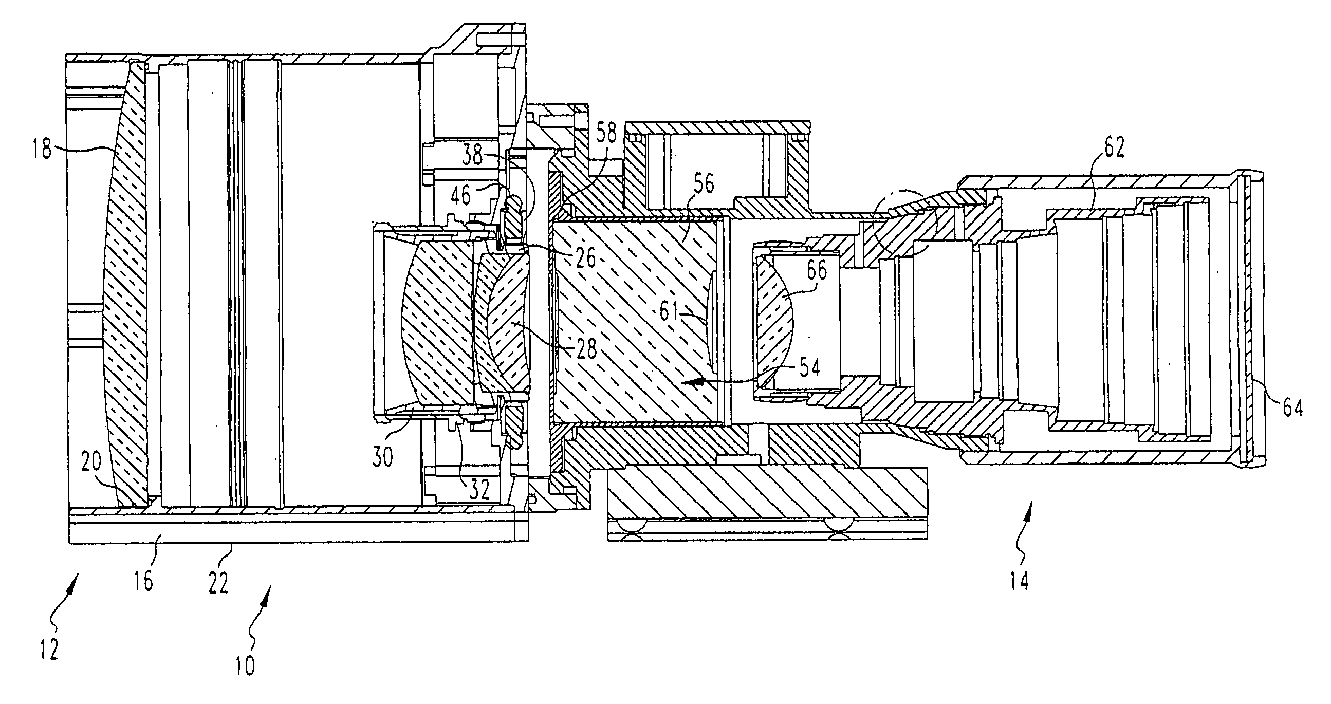
[0040]The present invention provides a night sight having a structure that permits the center line of the night sight to be mounted close to the center line of a barrel of a weapon with which the night sight is utilized, while also providing a large objective lens for maximized light gathering capability. The invention further provides a night sight having a structure that minimizes parallax.

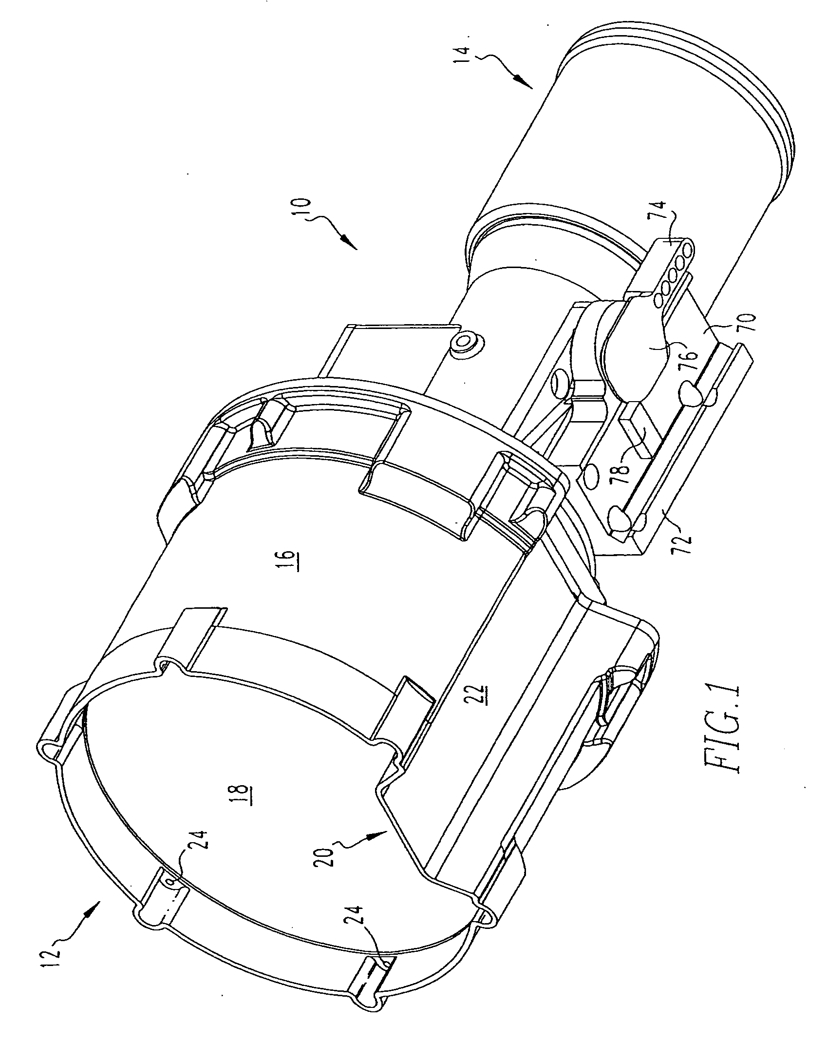
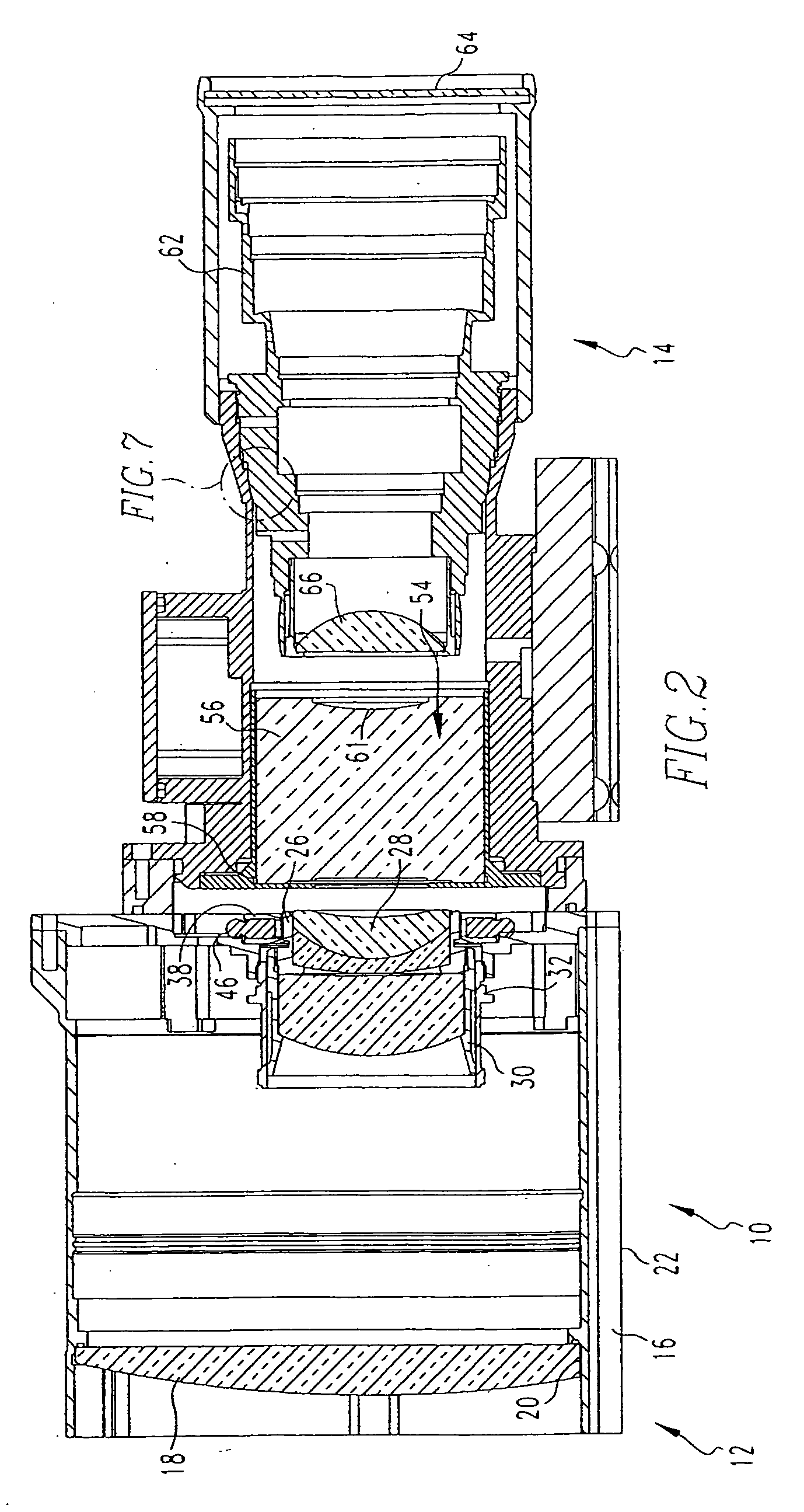
[0041]Referring to FIGS. 1 to 2, a night sight 10 is illustrated. The night sight 10 includes a forward end 12 which faces the target in use, and a back end 14 through which a shooter may view an image through the night sight 10, possibly through a daytime telescopic sight. A housing 16 holds the components of the night sight 10. An objective lens 18 is secured within the forward end 12. The objective lens 18 defines a cutaway section 20 along its bottom edge, corresponding to the cutaway section 22 defined along the bottom of the housing 16. The objective lens 18 is preferably held in sealing e...


PUM

PropertyMeasurementUnit
angleaaaaaaaaaa
center of curvatureaaaaaaaaaa
sizeaaaaaaaaaa

Abstract

A night sight includes a notched bottom portion, permitting the use of a large objective lens for maximized light gathering capability while also permitting the night sight to be mounted with its center line relatively close to the center line of the barrel of the weapon with which it is used. This configuration permits the night sight to be mounted so that its center line is the same as the center line of a daytime telescopic sight used in conjunction with the night sight. The night sight includes a focusing assembly having decreased sensitivity to tilt or decenter, and a collimator mounted within a spherical bearing so that the collimator may be precisely aligned during assembly of the night sight. The night sight thereby ensures that an image viewed through the night sight appears to originate from the same angle as that with which the image entered the objective lens, and further resists a need to compensate for parallax during aiming.

Description

CROSS REFERENCE TO RELATED APPLICATION[0001]The present application is a divisional application of U.S. Ser. No. 11 / 01 1,671, filed Dec. 14, 2004.BACKGROUND OF THE INVENTION[0002]1. Field of the Invention[0003]The present invention relates to night sights for firearms. More specifically, the present invention provides a night sight for use with a telescopic day sight, combining a large objective lens for maximum light gathering capability with the ability to mount the sight in line with the telescopic sight in a manner that resists parallax.[0004]2. Description of the Related Art[0005]The problem of aiming a firearm at night is often encountered by military and law enforcement personnel. The use of a light source to illuminate the target—whether visible light or infrared—has the disadvantage of indicating the location of the shooter. Laser aiming devices carry the same disadvantage. The use of tritium illuminated sights, while making the sights more visible, fails to illuminate the ...

Claims


Application Information

Patent Timeline
Patent Type & Authority Applications(United States)
IPC IPC(8): F41G1/38
CPCF41G1/32Y10T29/49826G02B23/12
Inventor POCHAPSKY, EUGENEMAXIN, PAULWELSH, WILLIAM
Owner FLIR SURVEILLANCE
Why Eureka
Try Eureka