Coupling device, and image forming apparatus

a technology of coupling device and image forming apparatus, which is applied in the direction of electrographic process apparatus, gearing, instruments, etc., can solve problems such as image degradation

Active Publication Date: 2009-08-06
RICOH KK
View PDF8 Cites 104 Cited by
  • Summary
  • Abstract
  • Description
  • Claims
  • Application Information

AI Technical Summary

Problems solved by technology

Rotational irregularity of the developing roller 205g causes toner concentration irregularities resulting in image degradation.

Method used


Image

  • Coupling device, and image forming apparatus
  • Coupling device, and image forming apparatus
  • Coupling device, and image forming apparatus

Examples


Embodiment Construction

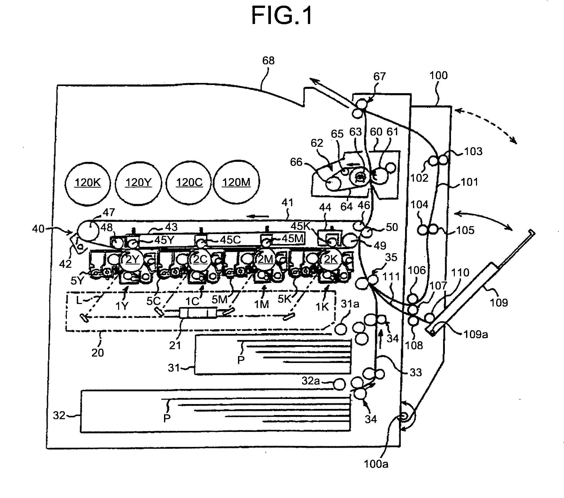
[0062]Exemplary embodiments of an electrophotographic printer (simply called a printer) will be explained as an image forming apparatus to which the present invention is applied.

[0063]First, the basic configuration of a printer will be explained below. FIG. 1 is a schematic of a printer according to an embodiment of the present invention. The printer includes four process cartridges 1Y, 1C, 1M, and 1K for generating toner images of yellow, cyan, magenta, and black (Y, C, M, and K). The process cartridges 1Y, 1C, 1M, and 1K use Y, C, M, and K toners as image forming substances for forming images, but have the same configuration in other respects, and are replaced after their service life. In the following, because the configurations of the process cartridges 1Y, 1C, 1M, and 1K are the same, the symbols Y, C, M, and K for identifying colors are omitted.

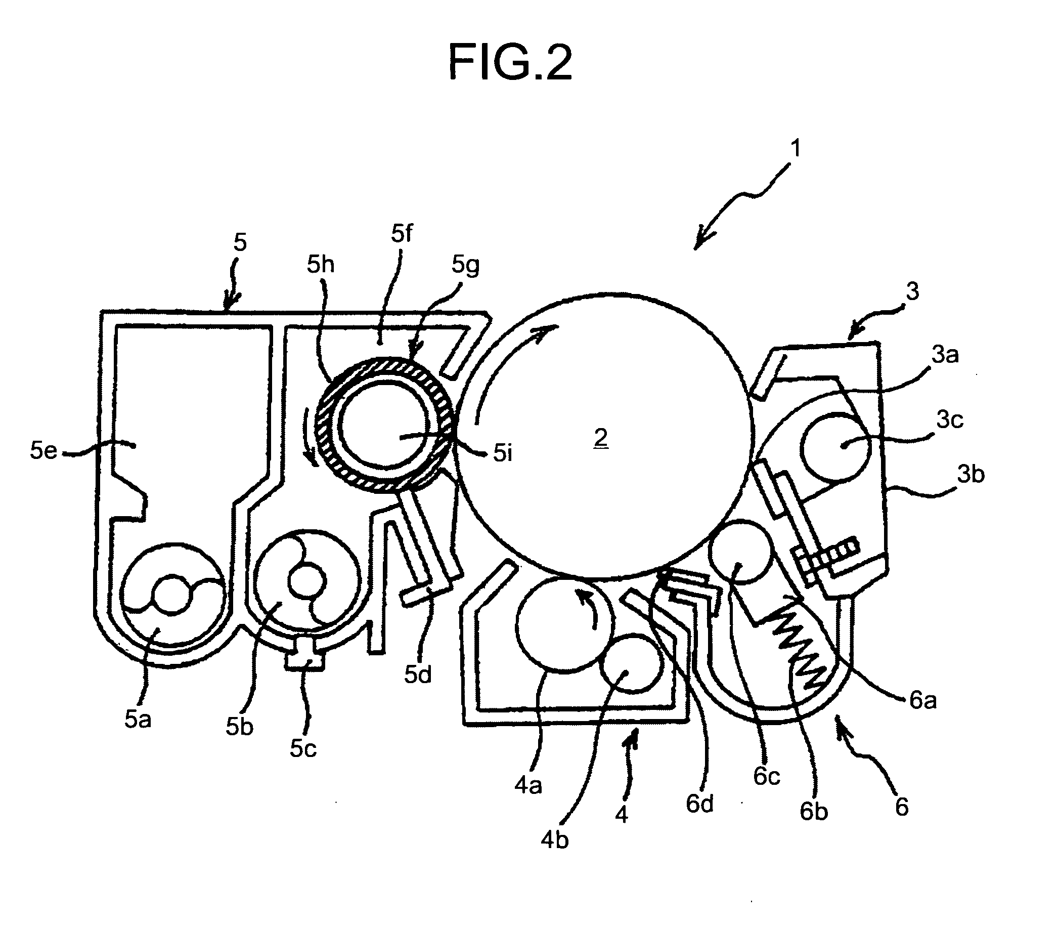
[0064]As shown in FIG. 2, a process cartridge 1 includes, in its frame (not shown), a drum-shaped photoconductor 2 as an image carrier...


PUM


Abstract

A coupling unit includes two constant velocity joints arranged in series in the shaft direction. The coupling unit couples a driven shaft and a drive shaft. Each constant velocity joint includes a ball non-retaining member and a ball retaining member. The ball non-retaining member has an annular space with one opened end and a plurality of track grooves extending in the shaft direction on an external wall surface of the annular space at a constant interval in a circumferential direction. The ball retaining member has a portion that engages with the annular space of the ball non-retaining member, and that retains a ball that slides along each of the track grooves formed in the ball non-retaining member.

Description

CROSS-REFERENCE TO RELATED APPLICATIONS[0001]The present application claims priority to and incorporates by reference the entire contents of Japanese application document 2007-262218 filed in Japan on Oct. 5, 2007 and Japanese priority document 2008-100781 filed in Japan on Apr. 8, 2008.BACKGROUND OF THE INVENTION[0002]1. Field of the Invention[0003]The present invention relates to a coupling device, and an image forming apparatus.[0004]2. Description of the Related Art[0005]A typical electrophotogrphic image forming apparatus forms an image by developing an electrostatic latent image formed on an image carrier using a developer and transferring the latent image to a recording material. A typical process cartridge houses, in its housing that is detachable with respect to an apparatus body of an image forming apparatus, at least one of a charging unit, a developing unit, and a cleaning unit that are arranged at a circumference of a drum-shaped photoconductor, and an image carrier.[00...

Claims


Application Information

Patent Timeline
Patent Type & Authority Applications(United States)
IPC IPC(8): G03G15/00F16H35/00
CPCG03G21/186G03G21/1864Y10T74/19G03G21/1647G03G2221/1657
Inventor TAKIGAWA, JUNYAKAMIYA, TAKUROSUGATA, HIDEAKIASAYAMA, YOSHIMI
Owner RICOH KK
Why Eureka
Try Eureka