Retractable compliant plate seals

a compliant plate and seal technology, applied in the direction of machines/engines, stators, liquid fuel engines, etc., can solve the problems of increased leakage path from the high pressure side, heat generation, seal and rotor wear,

Inactive Publication Date: 2009-08-06
GENERAL ELECTRIC CO
View PDF74 Cites 43 Cited by
  • Summary
  • Abstract
  • Description
  • Claims
  • Application Information

AI Technical Summary

Problems solved by technology

These gaps offer an increased leakage path from the high pressure side to the low pressure side of the seal.
However, labyrinth seal performance degrades over time as a result of transient events in which the stationary and rotating components interfere, rubbing the labyrinth teeth and permanently opening the seal clearance.
Contact between the compliant seal and the rotor causes seal and rotor wear, heat generation, and rotor-dynamic instabilities.

Method used


Image

  • Retractable compliant plate seals
  • Retractable compliant plate seals
  • Retractable compliant plate seals

Examples


Embodiment Construction

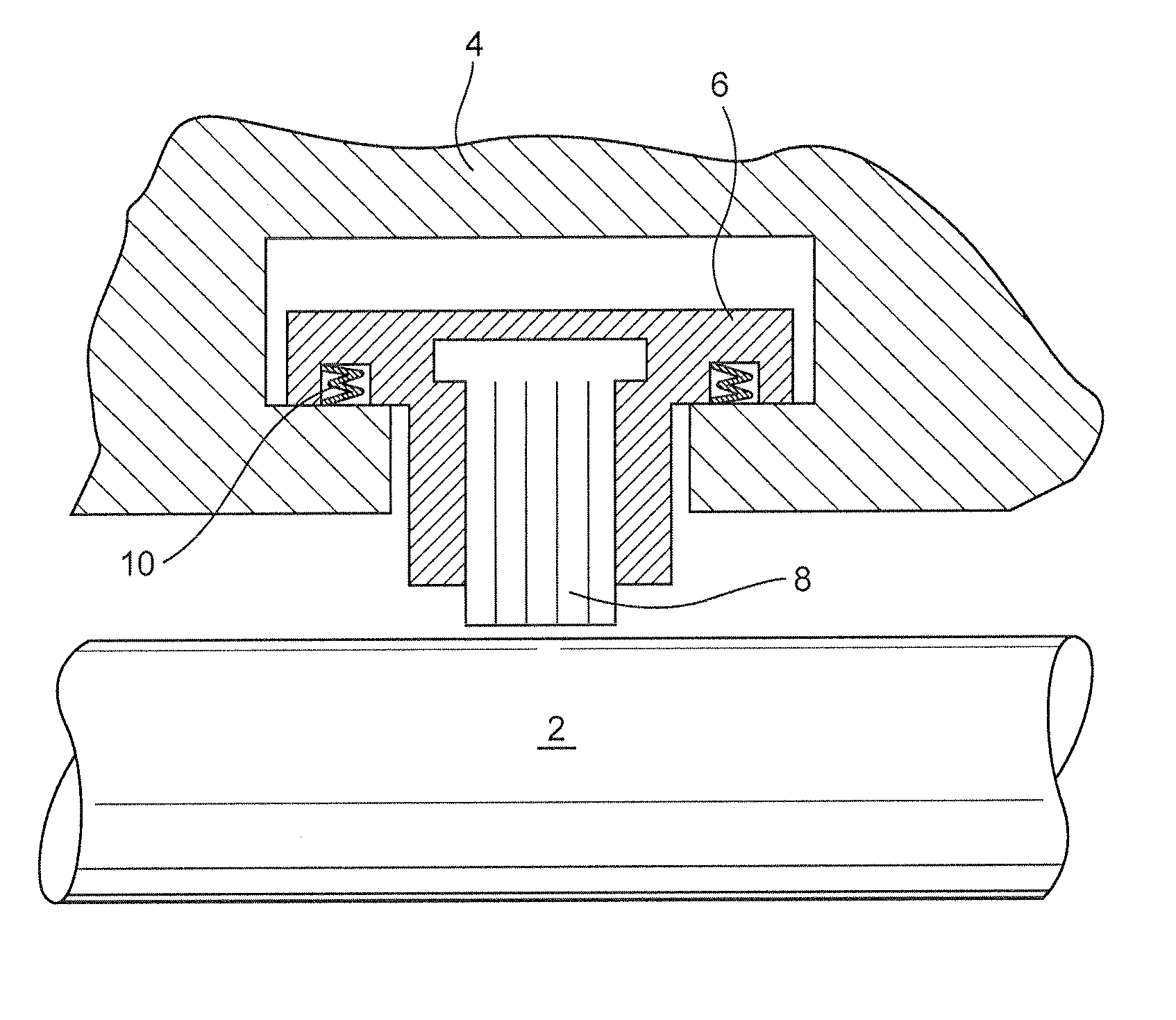
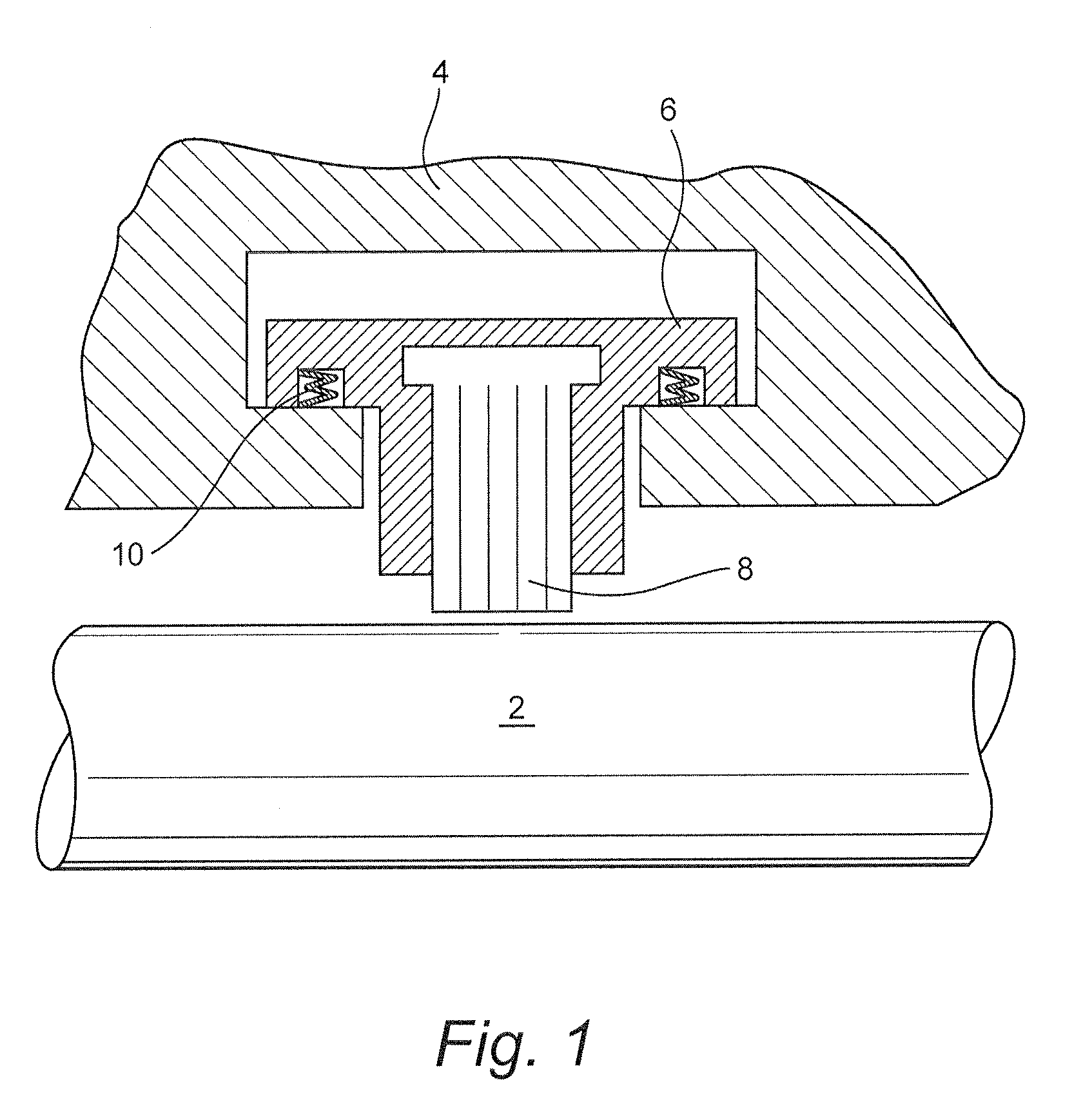
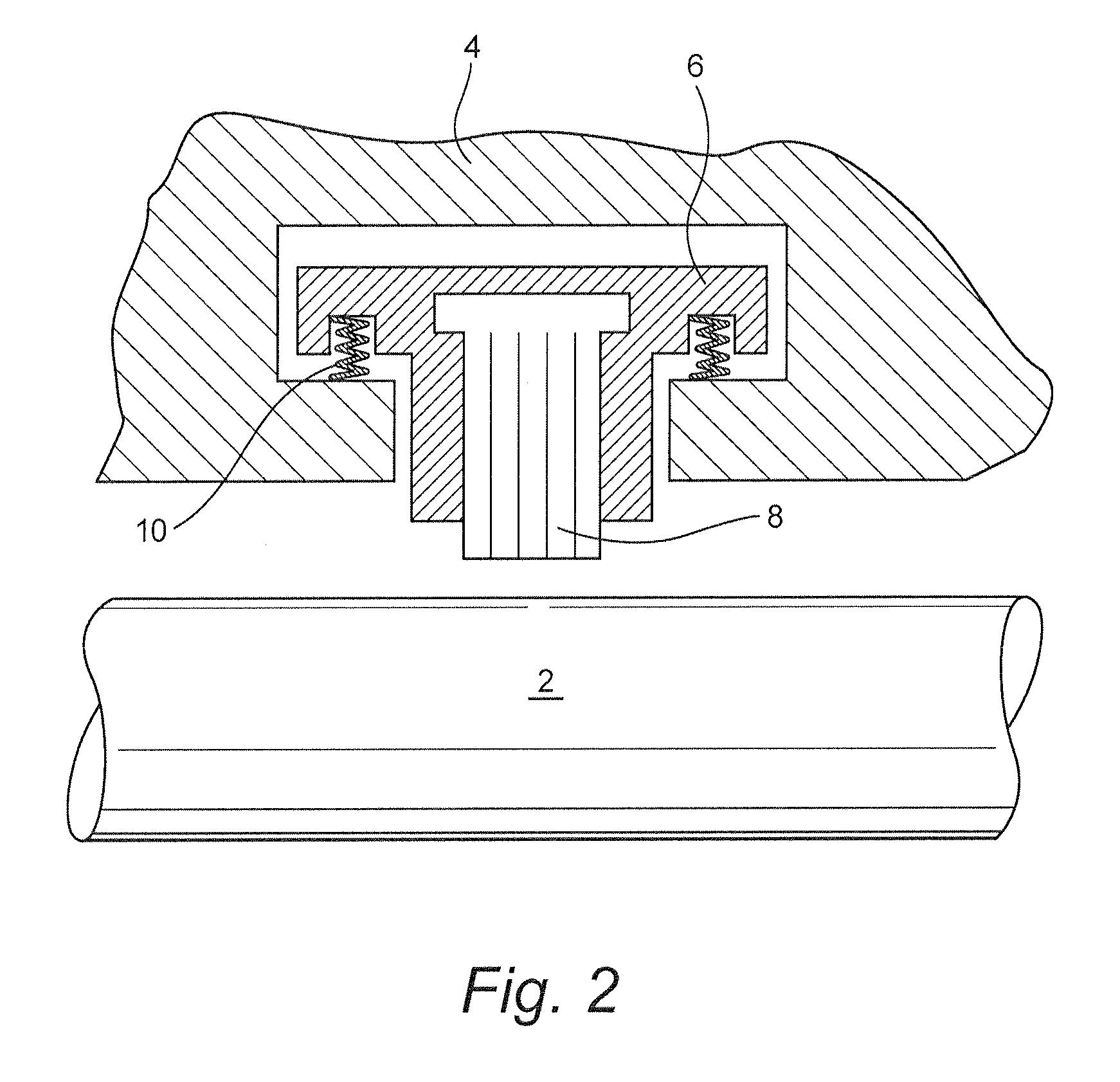
[0020]Referring to FIGS. 1 and 2, a turbo-machine may include a rotor 2 and a stator 4 which rotationally supports the rotor 2. A compliant plate seal housing 6 is supported in the stator 4 in an adjustable position by a spring system 10. The compliant plate seal housing 6 supports a compliant plate seal 8, which may be, for example, a shingle seal. As shown in FIG. 2, the retractable compliant plate seal is in the open position and the spring system 10 biases the compliant plate seal housing 6 away from the rotor 2 so that the compliant plate seal 8 does not contact the rotor 2. During startup and shutdown of the turbo-machine, the fluid pressure inside the machine is insufficient to overcome the radially outward spring force of the spring system 10 which keeps the seals open. Since the compliant plate seal 8 is most susceptible to contacting the rotor 2 during such transient periods, retracting the compliant plate seal 8 leads to a large radial gap between the compliant plate seal...


PUM


Abstract

A seal arrangement for sealing the space between a rotating element and a stationary element, the sealing arrangement comprising a compliant plate seal housing supported adjustably in the stationary element, the compliant plate seal housing supporting a compliant plate seal; and a spring system provided between the compliant plate seal housing and the stationary element to bias the compliant plate seal housing in a direction away from a surface of the rotating element. Alternatively, or additionally, one or more actuators may be provided to move the compliant plate seal housing in a direction away from a surface of the rotating element.

Description

[0001]The present invention relates to retractable compliant plate seals. In particular, the present invention relates to retractable compliant plate seals for use in turbo-machinery.BACKGROUND OF THE INVENTION[0002]Compliant plate seals are used to provide dynamic sealing between a rotor, for example a rotating shaft, and a stator, for example a static shell, casing or housing. Compliant plate seals are used in turbo-machinery to provide good sealing, non-contacting operation and high pressure capability. Examples of compliant plate seals are disclosed, for example, in U.S. Pat. Nos. 6,343,792 and 6,976,680.[0003]In the leaf seal design discussed above, the geometry requires that if the leaves are packed tightly at the tips, gaps will remain between the leaves close to the seal root. These gaps offer an increased leakage path from the high pressure side to the low pressure side of the seal.[0004]It is also known to radially position seal segments in a circumferential array between ...

Claims


Application Information

Patent Timeline
Patent Type & Authority Applications(United States)
IPC IPC(8): F01D11/02
CPCF05D2260/38F16J15/441F16J15/3292
Inventor TURNQUIST, NORMAN A.BAILY, FREDERICK G.COUTURE, JR., BERNARD A.MORTZHEIM, JASON P.FEENY, SEAN D.ADIS, WILLIAM E.AWTAR, SHORYAVERMA, NIKHIL K.
Owner GENERAL ELECTRIC CO
Why Eureka
Try Eureka