Direct metering fuel control with integral electrical metering pump and actuator servo pump

a technology of direct metering and fuel control, which is applied in the direction of positive displacement liquid engines, piston pumps, ignition of turbine/propulsion engines, etc., can solve the problems of increasing system complexity and cost, affecting the overall system weight and complexity, and suffering certain drawbacks

Active Publication Date: 2009-08-13
HONEYWELL INT INC
View PDF8 Cites 37 Cited by
  • Summary
  • Abstract
  • Description
  • Claims
  • Application Information

AI Technical Summary

Benefits of technology

[0006]In one embodiment, and by way of example only, a fuel supply system includes an electric motor, a fuel metering pump, a servo-flow pump, and a controller. The electric motor is adapted to receive electrical current and is configured, upon receipt of the electrical current, to supply a drive force. The fuel metering pump is coupled to the electric motor to receive the drive force supplied therefrom, and is responsive to the drive force to supply fuel. The servo-flow pump is coupled to the electric motor to receive the drive force supplied therefrom, and is responsive to the drive force to supply fuel. The controller is adapted to receive one or more signals representative of a desired fuel flow rate and is operable, in response thereto, to control the electrical current supplied to the electric motor such that the drive force supplied by the electric motor causes the fuel metering pump to supply fuel at the desired fuel flow rate.

Problems solved by technology

Nonetheless, it can suffer certain drawbacks.
For example, the metering valve and bypass valve can add to overall system weight and complexity.
Moreover, control of the metering valve and bypass valve can result in increased system complexity and cost.
Yet, efforts to implement direct fuel metering control systems have also been impeded by the certain drawbacks.
Thus, actuator operation can cause a droop in the fuel supplied to the engine, and thus an undesirable engine speed droop.
It is also postulated that such fuel supply variations to the engine could yield unpredictable, and potentially less controllable, engine transients.
This solution, however, exhibits its own drawbacks.
In particular, the independent servo pump and its associated drive mechanism (e.g., a motor) and control mechanism (e.g., controller) increase overall system weight and costs.
This solution also exhibits drawbacks in that it may rely on the use of a pressurizing valve, and the number of secondary loads that may be compensated for may be limited.

Method used


Image

  • Direct metering fuel control with integral electrical metering pump and actuator servo pump
  • Direct metering fuel control with integral electrical metering pump and actuator servo pump
  • Direct metering fuel control with integral electrical metering pump and actuator servo pump

Examples


Embodiment Construction

[0014]The following detailed description is merely exemplary in nature and is not intended to limit the invention or the application and uses of the invention. Furthermore, there is no intention to be bound by any theory presented in the preceding background or the following detailed description.

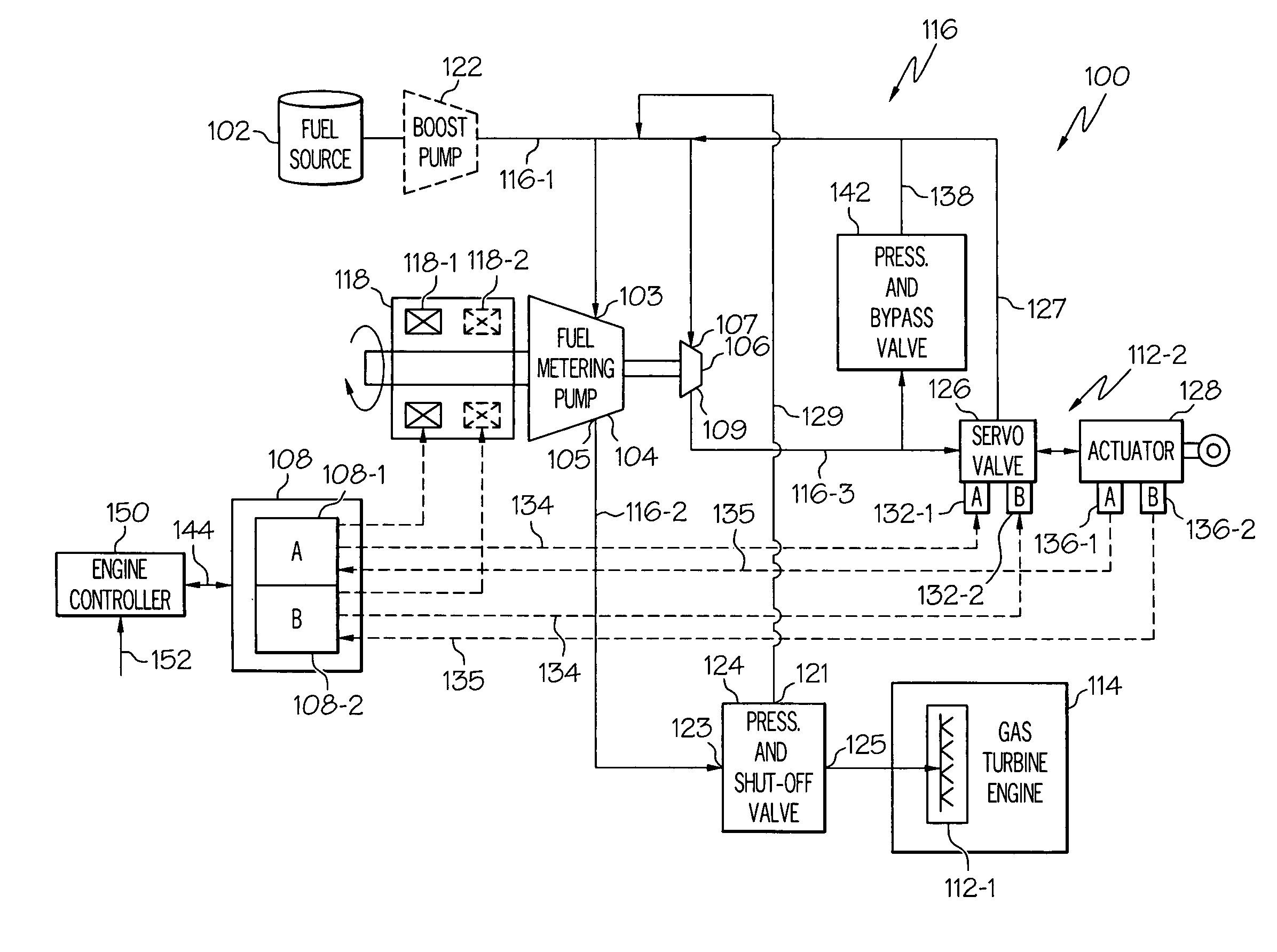
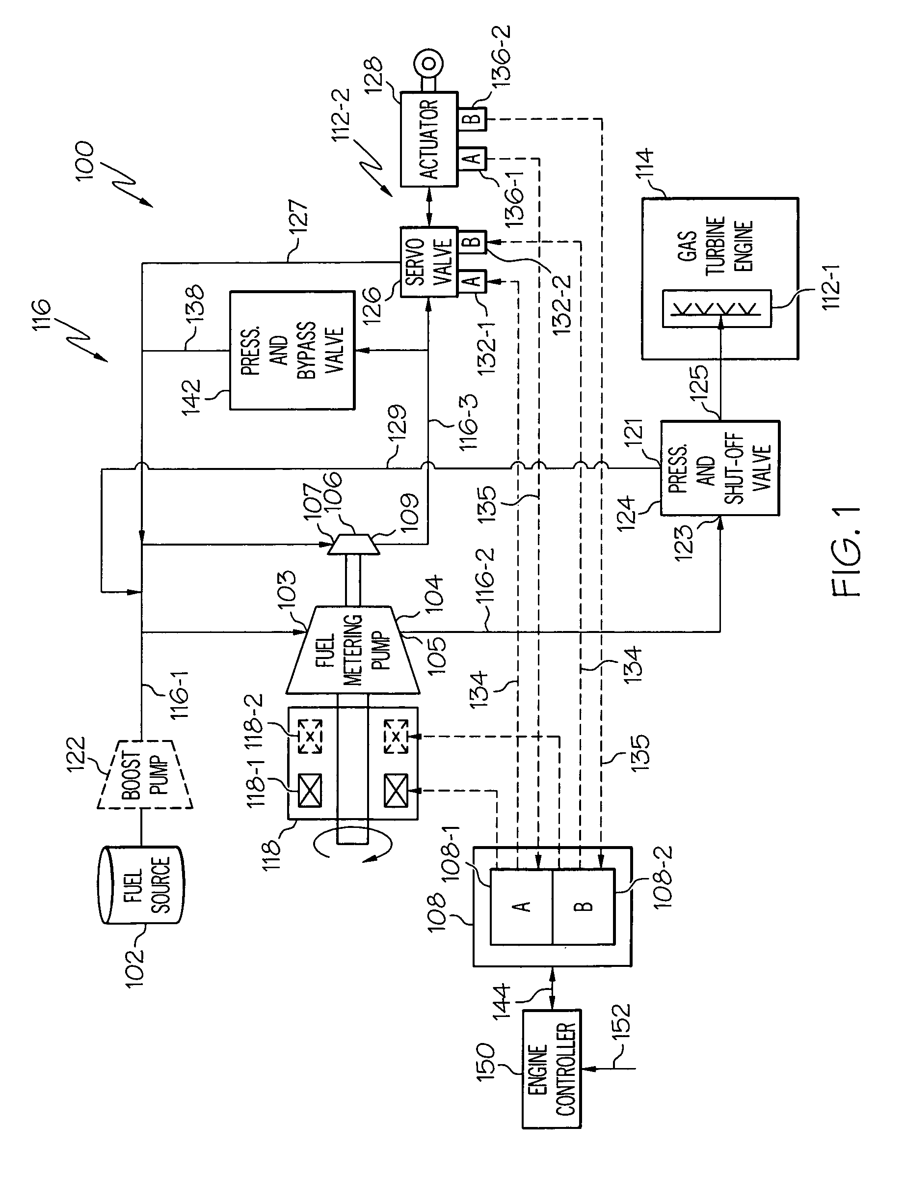
[0015]A direct metering fuel control system for a gas turbine engine, such as a turbofan jet aircraft engine, according to one exemplary embodiment, is depicted in FIG. 1. The system 100 includes a fuel source 102, a fuel metering pump 104, a servo-flow pump 106, and a controller 108. The fuel source 102, which is preferably implemented as one or more tanks, stores fuel that is to be supplied to a plurality of fuel loads 112 (e.g. 112-1, 112-2). It will be appreciated that the number and type of fuel loads 112 may vary. In the depicted embodiment, however, the fuel loads 112 include one or more gas turbine engine fuel manifolds 112-1, and a fluid-operated actuator 112-2. The one or more gas ...


PUM


Abstract

A fuel supply system includes a fuel metering pump and a servo-flow pump that are used to supply fuel to one or more fuel manifolds and one or more fluid-operated actuators, respectively. The fuel metering pump and the servo-flow pump are driven by the same electric motor(s).

Description

TECHNICAL FIELD[0001]The present invention relates to gas turbine engine direct metering fuel control and, more particularly, to a system and method of providing both burn flow and actuator flow using integral pumps.BACKGROUND[0002]Many gas turbine engine fuel supply systems include a fuel source, such as a fuel tank, and one or more pumps that draw fuel from the fuel source and deliver pressurized fuel to the fuel manifolds in the engine combustor via a main supply line. The main supply line may include one or more valves in flow-series between the pumps and the fuel manifolds. These valves generally include, for example, a main metering valve and a pressurizing-and-shutoff valve downstream of the main metering valve. In addition to the main supply line, many fuel supply systems also include a bypass flow line connected upstream of the metering valve that bypasses a portion of the fuel flowing in the main supply line back to the inlet of the one or more pumps, via a bypass valve. T...

Claims


Application Information

Patent Timeline
Patent Type & Authority Applications(United States)
IPC IPC(8): F02M37/08
CPCF02C7/222F02C7/236F02C9/30F02C9/22F02C9/26F02C7/26
Inventor MAHONEY, TIMOTHY D.PORTOLESE, LARRY A.
Owner HONEYWELL INT INC
Why Eureka
Try Eureka