
Automated Full Stripe Operations in a Redundant Array of Disk Drives

Inactive Publication Date: 2009-08-13
SUMMIT DATA SYST
View PDF4 Cites 25 Cited by
  • Summary
  • Abstract
  • Description
  • Claims
  • Application Information

AI Technical Summary

Benefits of technology

[0016]The present invention introduces a stripe handling process that improves memory access by avoiding the writing of partially calculated data to the P and Q stripelets. Each partial calculation requires a read followed by a write to the P or Q stripelet for every read of a data stripelet. Stripe handling performs calculations for the whole stripe, allowing the P or Q stripelet to be written only once, after all the data stripelets have been read. A reading of the P and Q stripelets is no longer necessary. Since multiple calculations are done in parallel, the data stripelets need to be read only once. Considering the 32 disk RAID 6 example, the same operation using the Stripe Handler requires 3840 data reads, 128 P writes, and 128 Q writes, resulting in a total of 4096 DMA operations of 512 bytes each, versus 23,040 DMA operations for a conventional RAID 6 system. The need to pre-fill the P and Q stripelets in memory with zeroes is also eliminated. Processor overhead is also improved by creating one command versus 60 partial commands.

Problems solved by technology

Since the RAID is now depicting a virtual disk consisting of multiple physical disks, there is a higher probability of one the individual physical disks failing.
If, however, there is a failure reading the requested data, then all the remaining data of the stripe needs to be read, to calculate the requested data.
For operations that write data to the RAID'ed disks, however, performance can be adversely affected due to the P and Q calculations necessary to maintain redundant information per stripe of data.
Although, full stripe writes increase performance by reducing the number of disk accesses, the performance is gated by certain bandwidth limitations of the processor and the memory accesses in the controller during the P and Q calculations.
However, the process is memory intensive—2 reads from data are required, as well as multiple read / writes from parity.
Further, the process is microprocessor intensive, requiring up to 8 separate memory-to-memory operations.

Method used


Image

  • Automated Full Stripe Operations in a Redundant Array of Disk Drives
  • Automated Full Stripe Operations in a Redundant Array of Disk Drives
  • Automated Full Stripe Operations in a Redundant Array of Disk Drives

Examples


Embodiment Construction

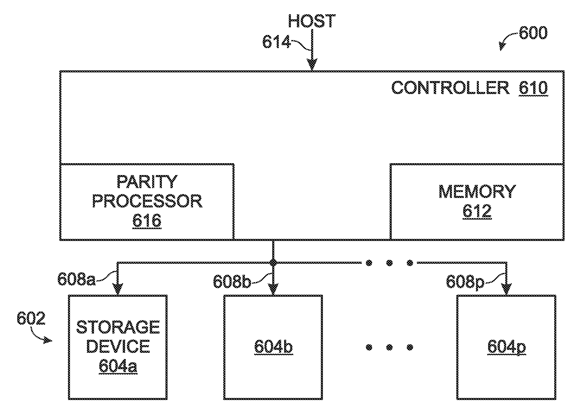
[0030]FIG. 6 is a schematic block diagram depicting a system for automating full stripe operations in a redundant data storage array. The system 600 comprises an array 602 of redundant data storage devices 604a though 604p, where p is not limited to any particular value. Each device 604a-604p has a controller interface for reading and writing data on lines 608a through608p, respectively. A controller 610 is shown with a memory 612 and a storage device interface on line 608. The controller 610 accumulates a parity product associated with an information stripe of data, and stores the parity product in the memory 612 in a single write operation, subsequent to accumulating the parity product. Then, the stored parity product can be written into a storage device 604. In one aspect, the array 602 of redundant data storage devices is a redundant array of disk drives (RAID). Then, the controller 610 is a RAID controller with an embedded controller memory 612 and a RAID interface.

[0031]The RA...


PUM


Abstract

A system and method are provided for automating full stripe operations in a redundant data storage array. In a redundant storage device controller, a parity product is accumulated that is associated with an information stripe. The parity product is stored in controller memory in a single write operation. A stored parity product is then written in a storage device. The parity product may be accumulated in a RAID controller, stored in a RAID controller memory, and written in a RAID. For example, the controller may receive n data stripelets for storage. The parity product is accumulated by creating m parity stripelets, and the m parity stripelets are written into the controller memory in a single write operation. Alternately, the controller may receive (n+m−x) stripelets from a RAID with (n+m) drives, recover x stripelets, and write x stripelets into controller memory in a single write operation.

Description

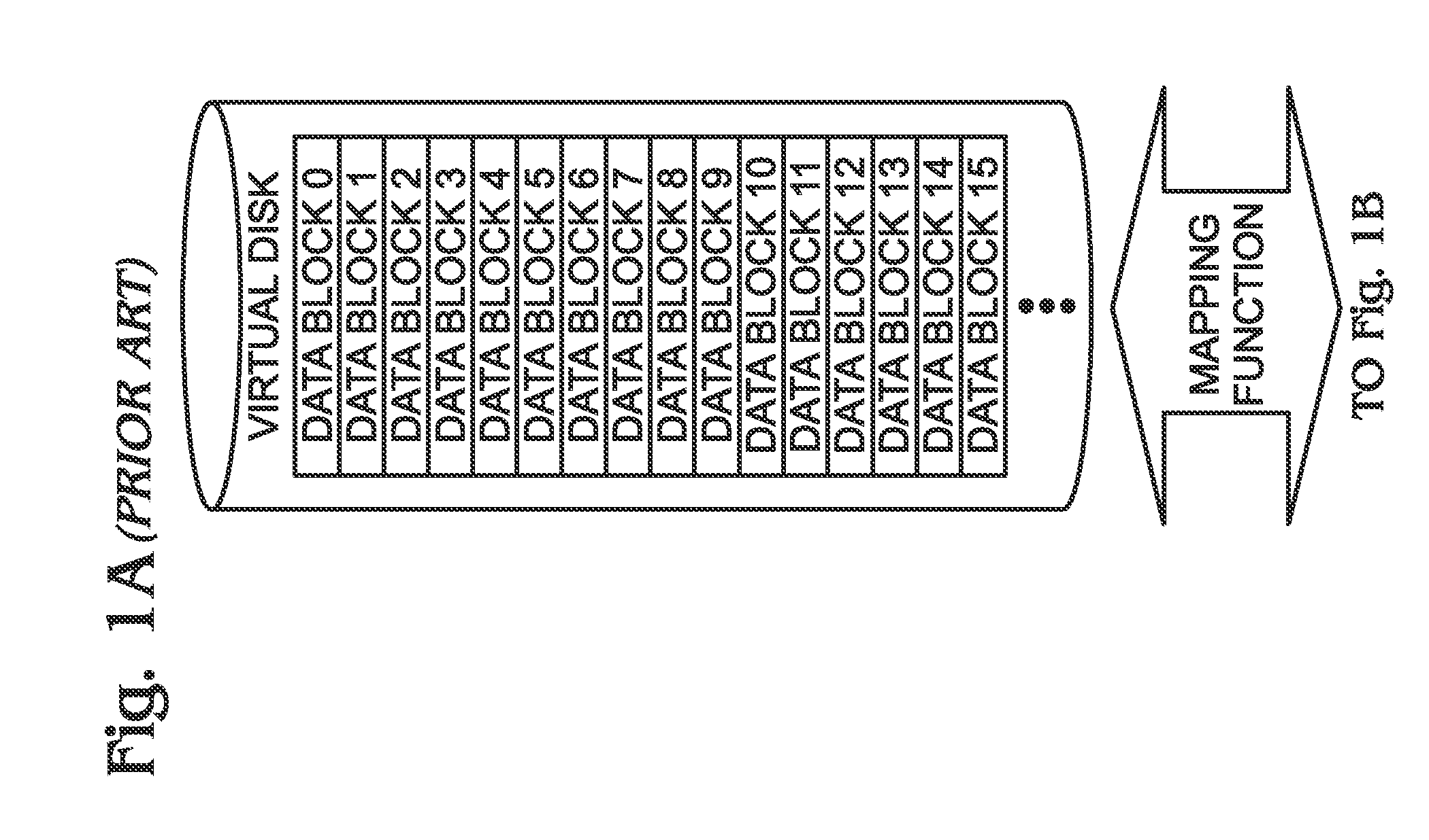
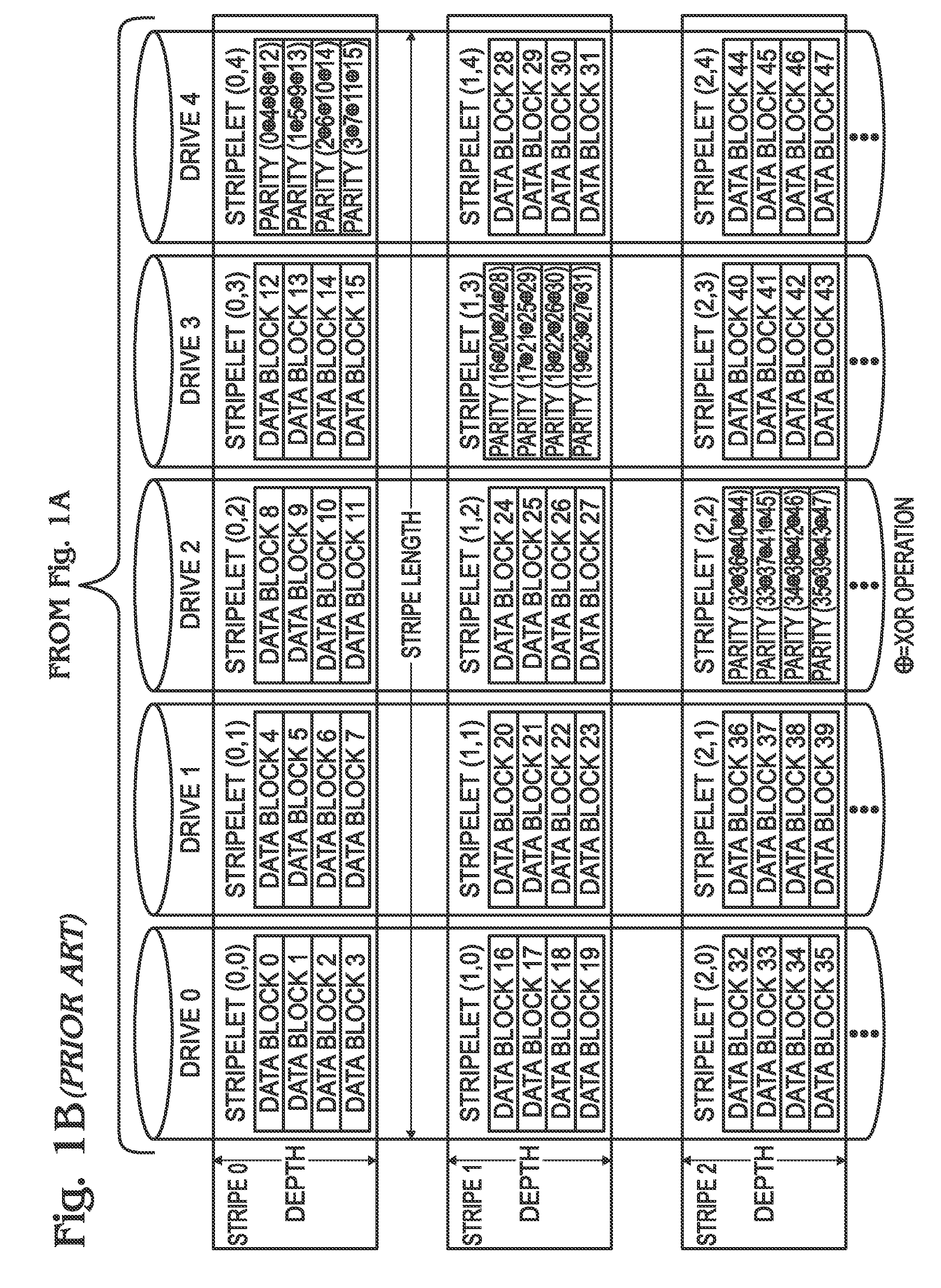
BACKGROUND OF THE INVENTION[0001]1. Field of the Invention[0002]This invention generally relates to data storage and, more particularly, to a system and method for automating full stripe operations in a redundant array of disk drives (RAID).[0003]2. Description of the Related Art[0004]FIGS. 1A and 1B are diagrams depicting a RAID 5 system (prior art). RAID 5 and RAID 6 are well known as systems for the redundant array of independent disks. Instead of distributing data “vertically” (from lowest sector to highest) on single disks, RAID 5 distributes data in two dimensions. First, “horizontally” in a row across n number of disks, then “vertically” as rows are repeated. A row consists of equal “chunks” of data on each disk and is referred to as a “stripe”. Each chunk of data, or each disk's portion of the stripe, is referred to as a stripelet.[0005]For RAID 5, one of the stripelets is designated as a parity stripelet. This stripelet consists of the XOR of all the other stripelets in the...

Claims


Application Information

Patent Timeline
IPC IPC(8): G06F11/10
CPCG06F11/1076G06F2211/1057G06F2211/1054
Inventor BALOUN, DOUGBISKUP, RICHARD
Owner SUMMIT DATA SYST
Learn More