Brake wear measurement system

a technology of wear measurement and brake wear, applied in the field of electronic braking systems, can solve problems such as inherently impreciseness, and achieve the effect of small linear displacemen

Active Publication Date: 2009-08-20
THE BF GOODRICH CO
View PDF10 Cites 29 Cited by
  • Summary
  • Abstract
  • Description
  • Claims
  • Application Information

AI Technical Summary

Benefits of technology

[0010]In accordance with another aspect, a brake measurement system comprises a linkage assembly operatively coupled to a moveable member of a brake assembly, and a linear displacement sensor operatively coupled to the linkage assembly. Movement of the moveable member is converted by the linkage assembly into a linear displacement sensed by the linear displacement sensor. The linkage assembly includes a first piston/cylinder, the piston of the first piston/cylinder arrangement adapted for movement in response to movement of the moveable member. A second piston/cylinder arrangement is fluidly connected to the first piston/cylinder arrangement such that movement of the respective pistons of each piston/cylinder arrangemen...

Problems solved by technology

Such arrangement requires a visual inspection of...

Method used


Image

  • Brake wear measurement system
  • Brake wear measurement system
  • Brake wear measurement system

Examples


Embodiment Construction

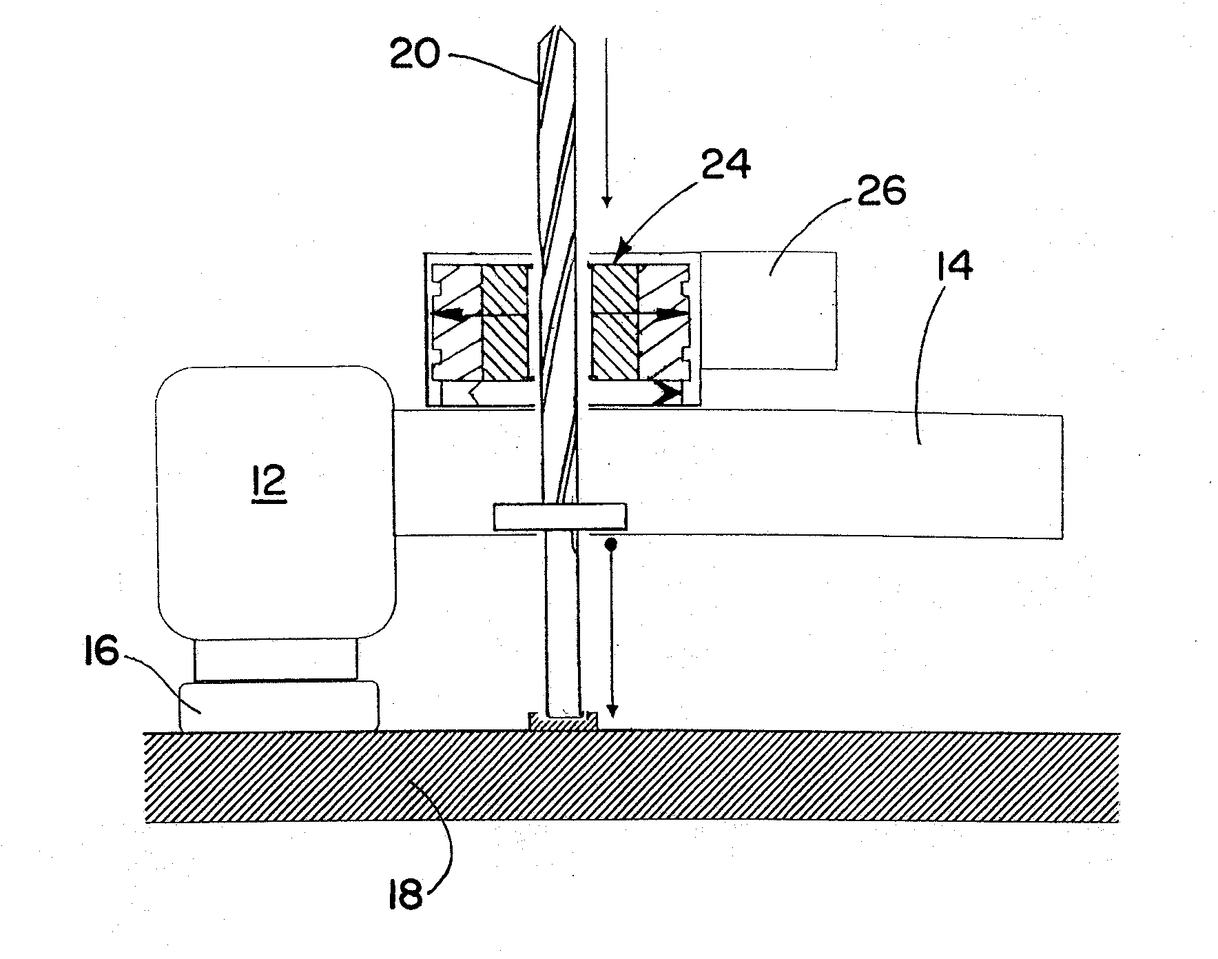
[0027]The present invention will now be described with reference to the drawings, wherein like reference labels are used to refer to like elements throughout.

[0028]The present invention relates to a brake wear measurement system incorporating an electrical wear sensor. Since a primary use of the brake wear measurement system is in conjunction with aircraft brakes, a feature of the present invention is the ability to tolerate the extremely harsh wheel and brake environment of an aircraft. In particular, non-axial vibration levels are often very high in aircraft brake systems. The brake wear measurement systems of the present invention are very robust to sustain such vibration levels as well as to operate in the harsh environment.

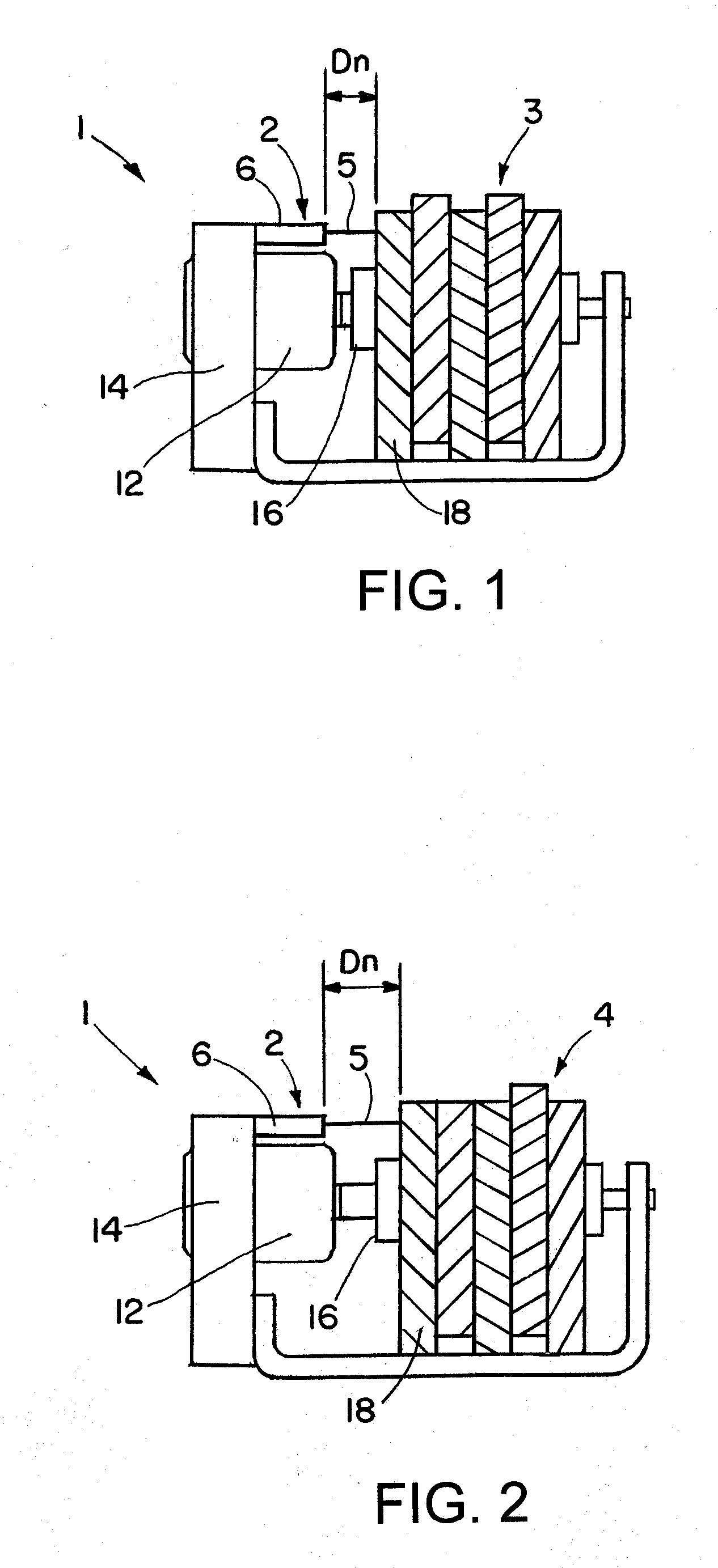
[0029]With reference to FIGS. 1 and 2, a brake actuator assembly 1 including an exemplary brake wear measurement system 2 in accordance with the invention is illustrated in relation to a new brake disk stack 3 (FIG. 1) and a worn brake disk stack 4 (FIG. 2). ...


PUM


Abstract

A brake measurement system that utilize angular and/or linear displacement sensors to measure movement of a member operatively coupled to a movable member of a brake, wherein displacement of the movable member of the brake is indicative of brake wear. The system can include a twisted spline member operatively coupled to a moveable member of a brake assembly, and an angular displacement sensor operatively coupled to the twisted spline member. Movement of the moveable member is converted by the twisted spline member into an angular displacement sensed by the angular displacement sensor.

Description

RELATED APPLICATIONS[0001]This application claims the benefit of U.S. Provisional Application Nos. 61 / 028,539 filed on Feb. 14, 2008, and 61 / 028,552 filed on Feb. 14, 2008, both of which are hereby incorporated by reference herein.FIELD OF THE INVENTION[0002]The invention herein described relates generally to brake control systems, more particularly to electronic braking systems, and still more particularly to aircraft braking systems.BACKGROUND[0003]Present day aircraft brake systems have employed wear pin indicators to measure overall wear of the brake disk stack. As the brake disks wear, the collective axial thickness thereof will decrease. Brake wear is indicated by the length of the pin relative to a reference plate. In a typical arrangement the length of the pin decreases as the brake wears. Such arrangement requires a visual inspection of the pin to determine wear and is inherently imprecise.[0004]U.S. Pat. No. 7,108,107 to Ralea provides a system for electrically measuring b...

Claims


Application Information

Patent Timeline
IPC IPC(8): F16D55/36
CPCF16D66/026F16D55/36F16D55/38
Inventor CAHILL, ERIC DANIEL
Owner THE BF GOODRICH CO
Why Eureka
Try Eureka