Electronic Coin Checker

Inactive Publication Date: 2009-08-20
WALTER HANKE MECHANISCHE WERKSTATTEN
View PDF11 Cites 1 Cited by
  • Summary
  • Abstract
  • Description
  • Claims
  • Application Information

AI Technical Summary

Benefits of technology

[0004]The present invention relates to a coin tester with a return channel open to the front plate of the coin tester, with which one avoids a false coin getting into the acceptance channel via the return channel.
[0005]By way of the fact that the deflector comprises means for clamping a coin introduced through the return opening, preferably an upright edge, on activating an electromagnet which is in conn

Problems solved by technology

In this manner, false coins may circumvent

Method used


Image

  • Electronic Coin Checker
  • Electronic Coin Checker
  • Electronic Coin Checker

Examples


Embodiment Construction

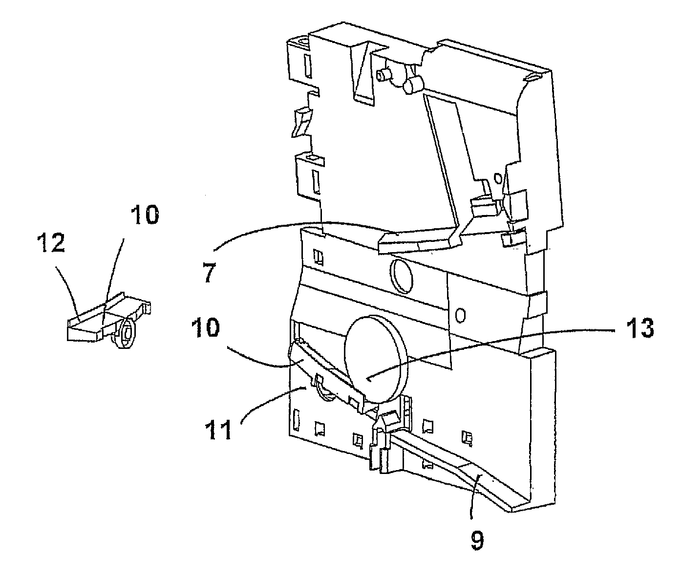
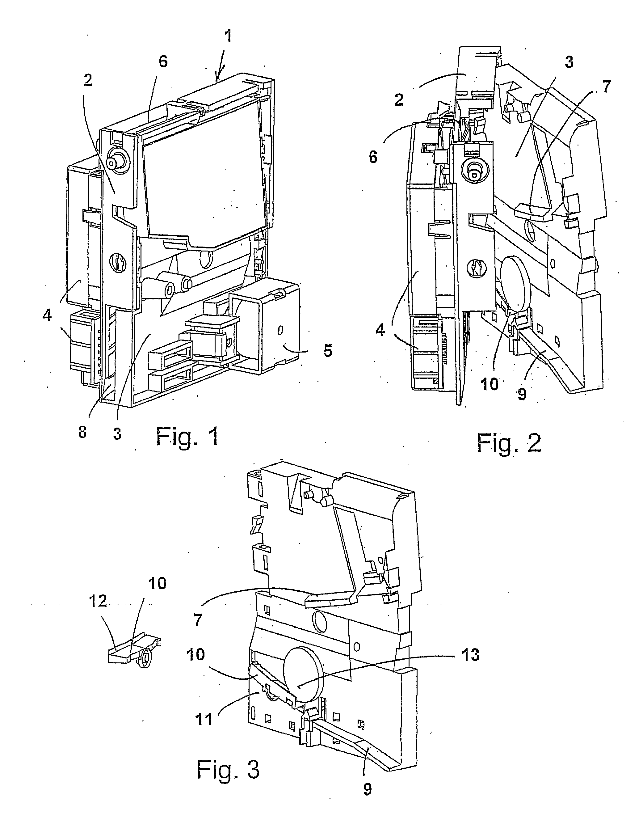
[0011]A coin tester is represented in FIG. 1, which comprises a housing 1 which consists of a base body 2 and a flap 3 covering the base body in a sandwich-like manner. The two component parts 2 and 3 are to be particularly well recognized in FIG. 2. The electrical, electronic and mechanical component parts 4, such as testing arrangements, control devices, circuit boards with electronic circuits and an electromagnet 5, are attached on the housing 1. A coin insert 6 is provided in the upper region of the housing 1, and a coin track 7 via which an inserted coin is led further, is formed in the flap 3. Test sensors which are not represented in more detail, are incorporated in the wall region of the coin track 7, and are connected to a control device. Furthermore, a return channel with a return opening 8 and a runner track 9 are to be recognized in FIG. 1 and FIG. 2, wherein the channel is formed by the runner track 9 and the delimiting housing walls.

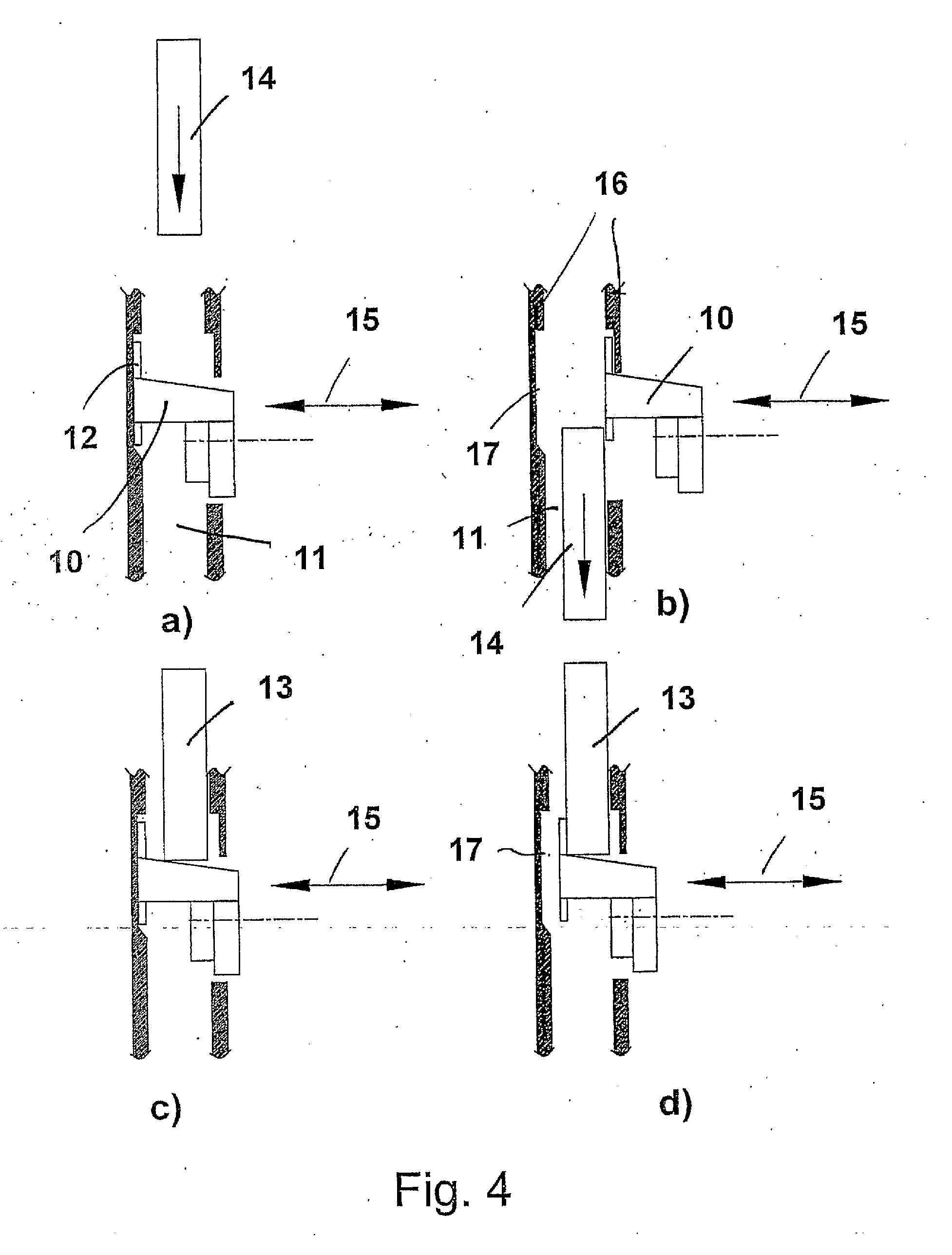
[0012]A deflector 10 which is in con...


PUM


Abstract

An electronic coin checker is disclosed, comprising a coin insert, a coin running track, in the region of which at least one checking device, for checking the coins, is arranged and a deflector. According to the result from the checking device, the deflector may be placed in a withdrawn position, opening the acceptance channel, or in an extended position, in which the coin is deflected into a return channel which ends in a return opening in the front region of the coin checker. The deflector comprises means for clamping which clamp a false coin introduced through the return opening in the extended state of the deflector, by means of withdrawing the deflector.

Description

FIELD OF THE INVENTION[0001]The present invention relates to an electronic coin tester.BACKGROUND OF THE INVENTION[0002]Electronic coin testers are generally known, and usually comprise a housing which is provided with a coin insert to which a coin run-in connects. Usually, test sensor arrangements are provided in the region of the coin run-in channel, which test an inserted coin with regard to its material characteristics, its size or other characteristics. A switching mechanism is activated by a control device, depending on the results of the testing, wherein the switching mechanism usually comprises a deflection element and an electromagnet. The deflection element is actuated by the electromagnet, between a position releasing an acceptance channel and a return position. In the known manner, the deflection element may be designed as a strip-like runner track piece which in the idle condition of the electromagnet is a component part of a return channel or return runner track, and w...

Claims


Application Information

Patent Timeline
IPC IPC(8): G07F1/04
CPCG07F1/047G07D5/00
Inventor GRIESE, ROLAND
Owner WALTER HANKE MECHANISCHE WERKSTATTEN
Why Eureka
Try Eureka