Vibration device, antidust device, camera, vibration device inspection method, method for manufacturing vibration device and vibration method

a technology of vibration device and anti-dust, which is applied in the direction of mechanical vibration separation, generator/motor, instruments, etc., can solve the problems of difficult to remove dust attached to the node, difficult to detect vibration accurately, and dust is shown in a taken imag

Inactive Publication Date: 2009-08-20
NIKON CORP
View PDF8 Cites 25 Cited by
  • Summary
  • Abstract
  • Description
  • Claims
  • Application Information

AI Technical Summary

Benefits of technology

[0013]Also, for example, the vibration device according to the present invention, number of the driving electrodes existing between adjacent two vibration nodes may be more than two.

Problems solved by technology

In recent years, in a lens interchangeable digital camera and the like, there are problems such that dust is shown in a taken image due to adherence of the dust on a surface of a filter of an image pick-up element.
However, according to conventional systems, since an acceleration of the standing wave occurred on a vibration node is so small, it has been difficult to remove dust attached on the node.
According to the conventional sensing electrode, for example, an output detected by the sensing electrode in a vibration mode such as overlapping a vibration node position and the sensing electrode, there is sometime difficult to detect the vibration accurately.

Method used


Image

  • Vibration device, antidust device, camera, vibration device inspection method, method for manufacturing vibration device and vibration method
  • Vibration device, antidust device, camera, vibration device inspection method, method for manufacturing vibration device and vibration method
  • Vibration device, antidust device, camera, vibration device inspection method, method for manufacturing vibration device and vibration method

Examples


first embodiment

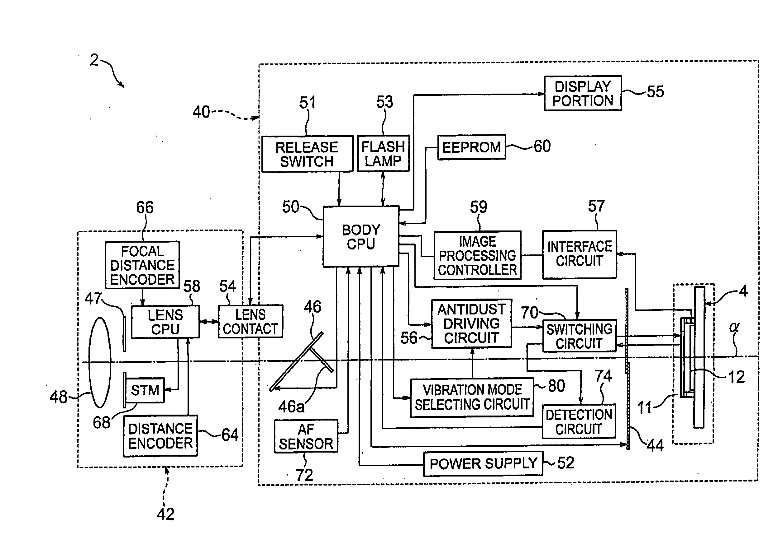
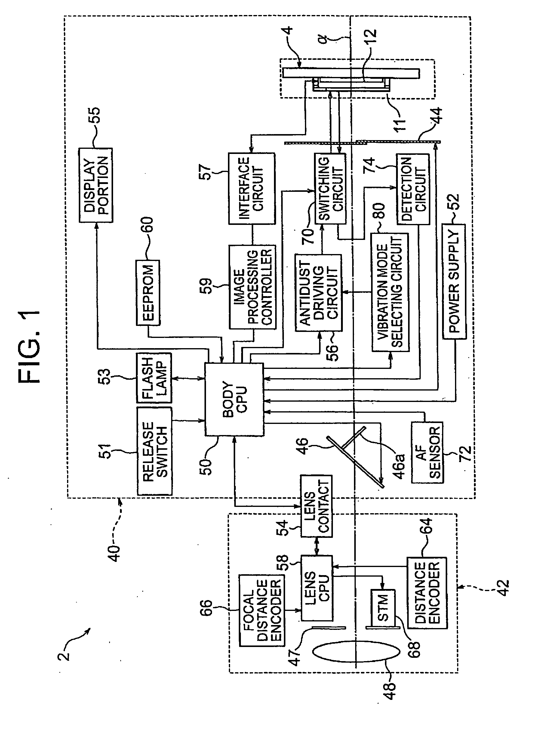
[0115]Firstly, whole constitution of a camera 2 of the present embodiment will be specified based on FIG. 1. An imaging element unit 4 is provided in a camera body 40 so that an antidust portion 11 crossing substantially vertical to an optical axis α of optical lens group 48. With respect to the antidust portion 11, it will be specified later. Note that, in the camera 2, it will be specified as a direction from the imaging element unit 4 to the optical lens group 48 is a front side of the optical axis α, and a direction from the optical lens group 48 to the imaging element unit 4 is a back side of the optical axis α.

[0116]A shown in FIG. 1, a lens barrel 42 is detachably mounted to the camera body 40. There is a camera, in which the lens barrel 42 and the camera body 40 are integrated such as a compact camera, thus, a type of camera is not particularly limited.

[0117]In the camera body 40, a shutter member 44 is provided at a front side of the optical axis α of the imaging element un...

second embodiment

[0228]FIG. 12A is a plane view of an antidust portion 11 according to a second embodiment of the present invention, FIG. 12B is a cross sectional view along a line XIIB-XIIB of FIG. 12A. As shown in FIG. 12A and FIG. 12B, the antidust portion 11 according to the second embodiment comprises two vibrators 20, 21. Note that, constitutions other than shown in FIG. 12A and FIG. 12B are similar with the camera 2 including the antidust portion 11 according to the first embodiment.

[0229]Namely, in the second embodiment, in addition to the vibrator 20 attached on one side of the long side direction L of the antidust filter 18, a second vibrator 21 is attached on another end of the long side direction L. The second vibrator 21 includes four sheets of a first to a fourth driving electrodes 33a to 33d which are insulated respectively, as similar with the vibrator 20. Also, as shown in a cross sectional view of FIG. 12B, the second vibrator 21 further comprises a common electrode 35 attached on ...

third embodiment

[0234]FIG. 13 is a block diagram showing a camera according to a third embodiment of the present invention. A camera 2 according to the third embodiment does not include a detection circuit 74 in a camera body 40. With respect to other constitutions, they are similar with the camera 2 according to the first embodiment shown in FIG. 1 and the like.

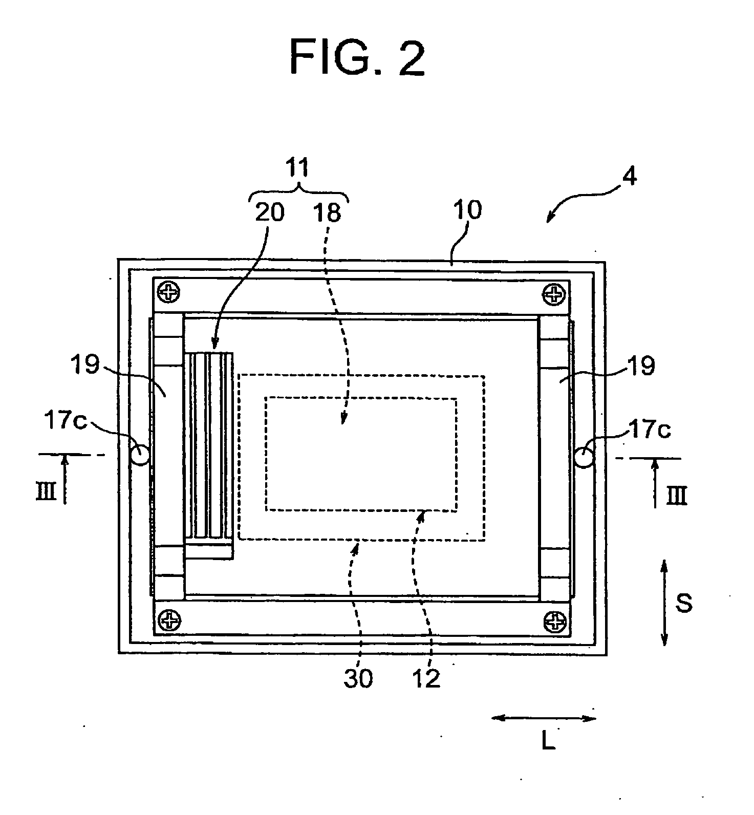
[0235]The camera 2 shown in FIG. 2 is connected with an inspection device 96 at the time of vibration inspection performed in manufacturing process and the like. A detection circuit 74 is provided with the inspection device 96, the detection circuit 74 is electrically connected to one of driving electrodes of a vibrator via a switching circuit 70.

[0236]Therefore, in the inspection operation of a flow chart of FIG. 10, the vibration signal shown in FIG. 11 is displayed to an inspection display portion 98 and the like such as monitor provided in the inspection device 96. In this manner, the camera according to the third embodiment has a simpl...


PUM


Abstract

A vibration device comprising; a vibrator which generates bending vibration on a predetermined member, a controller which controls a driver to drive the vibrator, wherein; the vibrator comprises a plurality of driving electrodes electrically insulated respectively, the controller controls the driver to make phases of driving signals respectively output to the plurality of driving electrodes changeable relatively and adjust an order of the bending vibration.

Description

BACKGROUND OF THE INVENTION[0001]1. Field of the Invention[0002]The present invention relates to a vibration device and the like, more precisely, relates to a vibration device and the like so as to occur vibration efficiently.[0003]2. Description of the Related Art[0004]In recent years, in a lens interchangeable digital camera and the like, there are problems such that dust is shown in a taken image due to adherence of the dust on a surface of a filter of an image pick-up element. In order to solve such problems, a system has been developed that an antidust member, to which a piezoelectric element is attached, is provided between an image pick-up element and an optical system, to remove the dust on the antidust member with a standing wave integrated on the antidust member by the piezoelectric element and the like (JP Patent Publication No. 2003-333395). Also, it has been known that there is another system comprising a sensing electrode to detect vibration status of a filter surface....

Claims


Application Information

Patent Timeline
Patent Type & Authority Applications(United States)
IPC IPC(8): H01L41/09H01L41/053G02B5/20G01R29/22
CPCB06B1/0603G02B7/1822G03B17/00G02B26/0825G02B7/183H04N23/811
Inventor OKAZAKI, MITSUHIRO
Owner NIKON CORP
Why Eureka
Try Eureka