Kirschner wire clamp

a wire clamp and wire technology, applied in the field can solve the problems of limited functionality, difficult handling of kirschner wire clamps known from prior art, and difficulty in carrying out satisfactory preliminary fixation of bone plates

Active Publication Date: 2009-08-27
STRYKER EURO OPERATIONS HLDG LLC
View PDF14 Cites 24 Cited by
  • Summary
  • Abstract
  • Description
  • Claims
  • Application Information

AI Technical Summary

Benefits of technology

[0032]These and other aspects of the present invention are explained and

Problems solved by technology

However, these Kirschner wires may be inadequate for fixation until final healing, so that subsequent positioning of bone plates needs to take place.
However, the Kirschner wire clamps known from prior a

Method used


Image

  • Kirschner wire clamp
  • Kirschner wire clamp
  • Kirschner wire clamp

Examples


Embodiment Construction

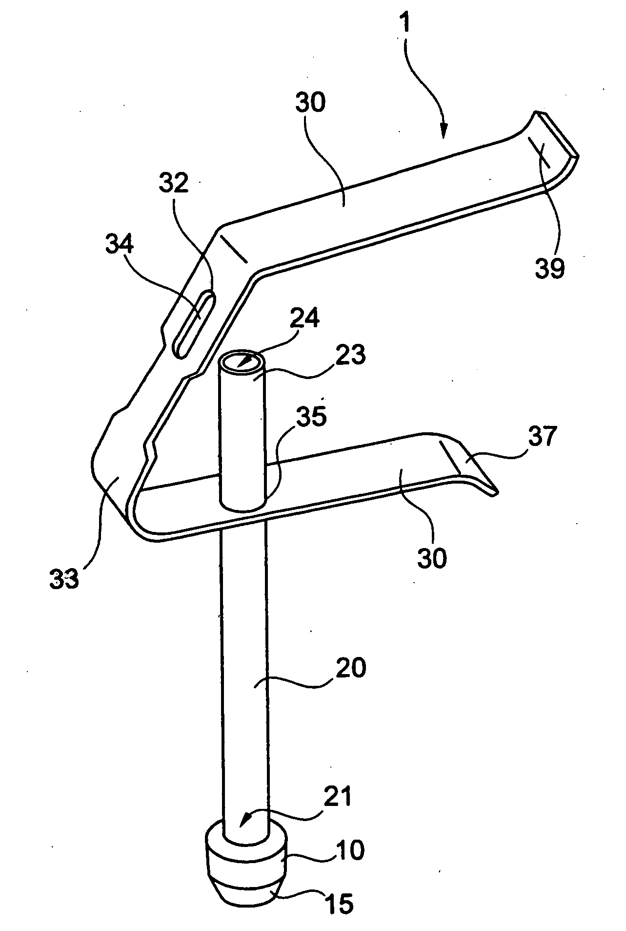
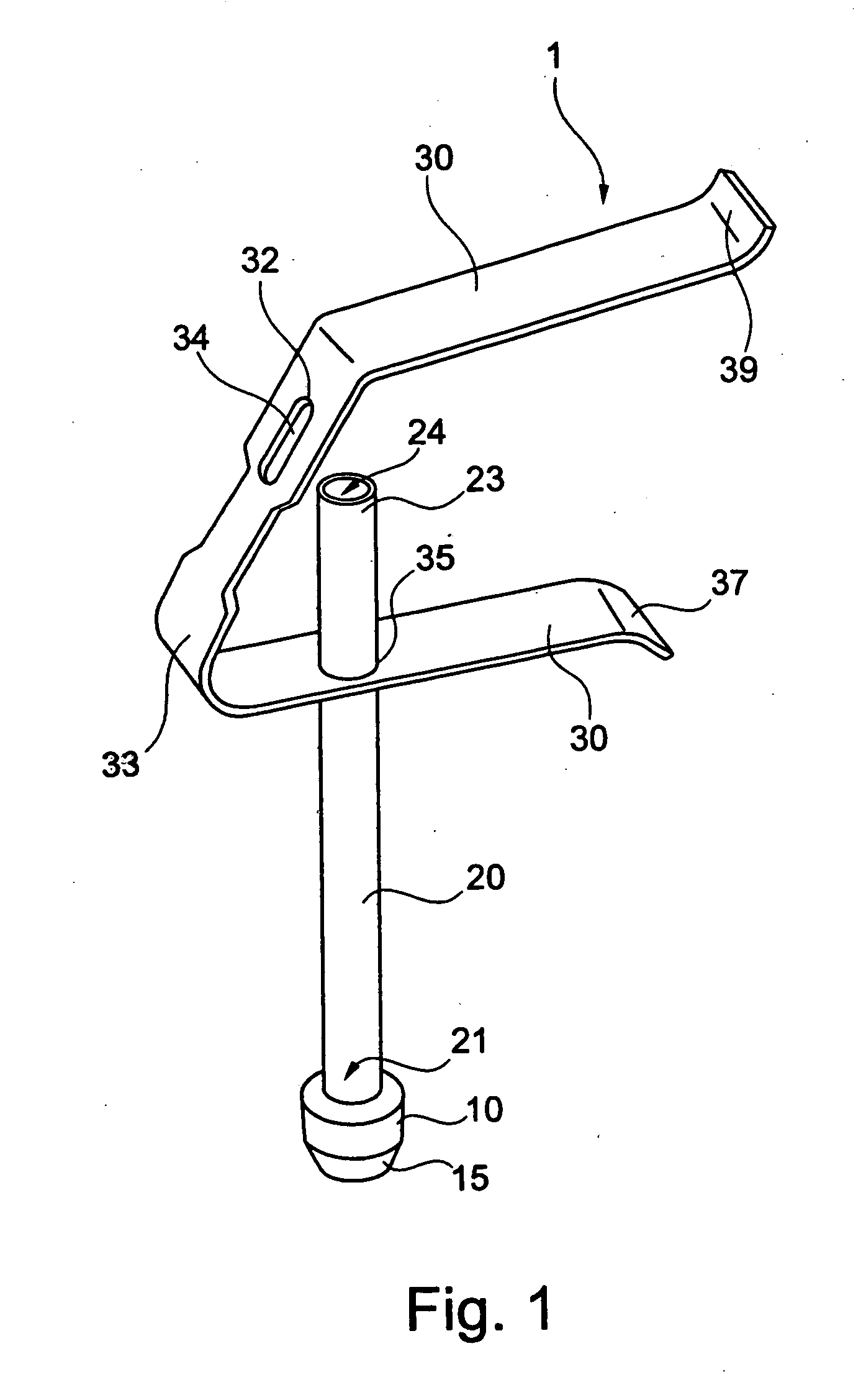
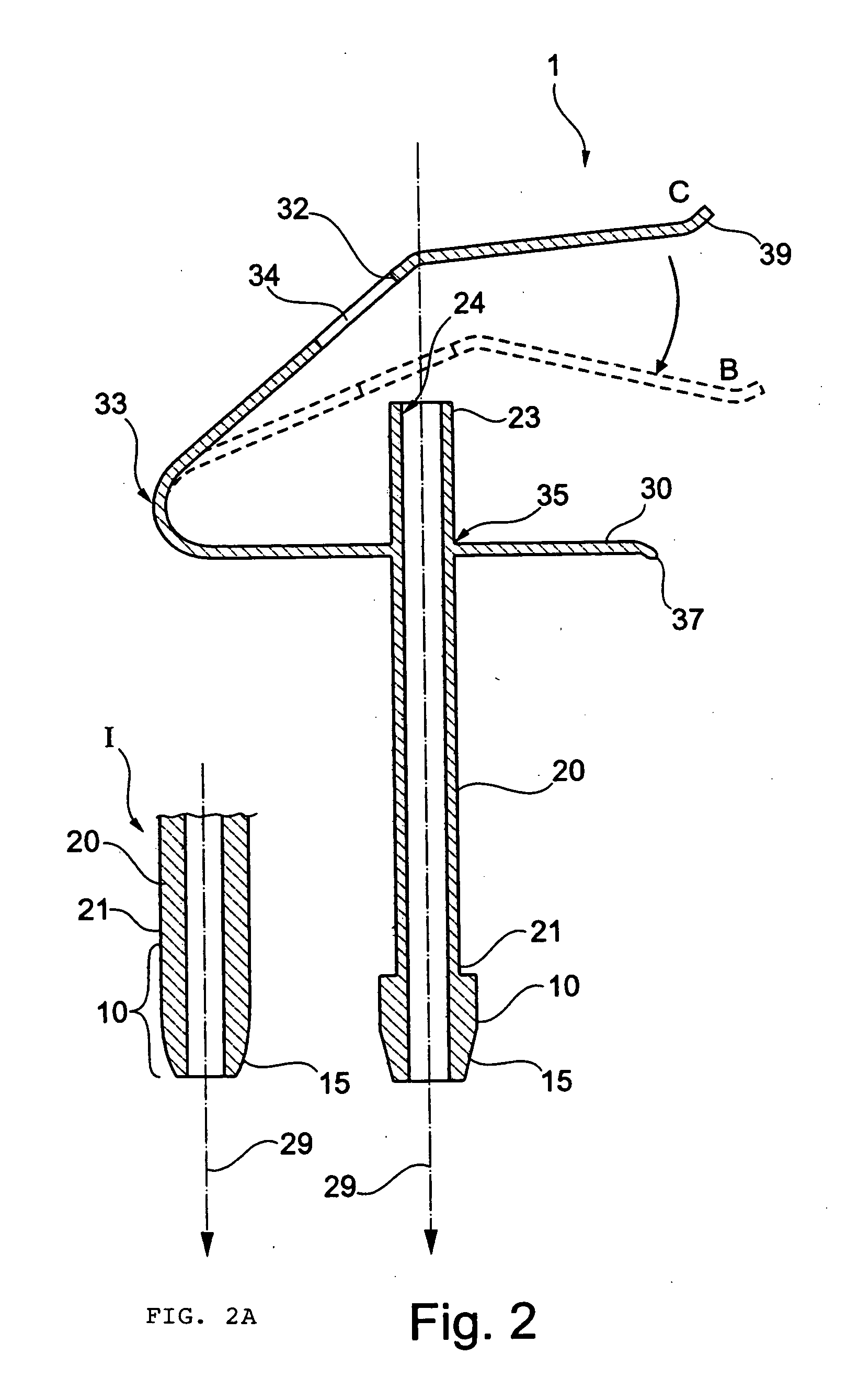
[0039]Referring to FIG. 1 there is shown a perspective view of a preferred Kirschner wire clamp 1 according to the invention. The Kirschner wire clamp 1 shown in FIG. 1 comprises a guide element 20. Furthermore, a base element 10 is provided, which is located in a first end region 21 of the guide element 20. In the preferred embodiment shown, the base element 10 comprises a diameter that exceeds that of the guide element. However, this is not mandatory. Instead, the base element can also be formed to the guide element so as to make a gradual transition, as shown in FIG. 2A in the tip section designated I. In this case that part which essentially is used to guide a Kirschner wire is to be understood to be the guide element, while the base element is understood to be the part which essentially is used as a foundation for the Kirschner wire clamp on the bone plate 50 as shown in FIG. 3. The exertion of force for fixing the bone plate 50 takes place by way of base element 10. In the emb...


PUM


Abstract

A Kirschner wire clamp is used to reliably and simply fix bone plates to a bone surface. The wire clamp consists of a tubular guide member for receiving a Kirschner wire. The guide member has a bore surrounded by a wall and a base for engaging a hole in a bone plate such as a bone screw hole. A spring clamp is mounted adjacent an open end of the tubular guide bore opposite the base which clamps the Kirschner wire to the guide member after the wire has been fixed in bone. The Kirschner wire clamp can be aligned simply and reliably by the guide member, and by the clamping mechanism, can be reliably fixed to the Kirschner wire.

Description

CROSS-REFERENCE TO RELATED APPLICATIONS[0001]This application claims the benefit of the filing date of German Utility Model Application No. 20 2008 000 914.6 filed Jan. 22, 2008.BACKGROUND OF THE INVENTION[0002]The present invention relates to a Kirschner wire clamp for positioning a bone plate, in particular a Kirschner wire clamp, which allows more precise, easier and simpler positioning of a bone plate on a bone surface.[0003]In the treatment of bone fractures it is helpful and sometimes necessary that, prior to fixation of a fracture by bone plates, the fracture itself is stabilized. This is, in particular, helpful or necessary in cases where the bone fracture not only comprises two fragments but a multitude of fragments. In this case it may be necessary to stabilize the multitude of fragments in their original position before fastening corresponding bone plates and bone screws for fixation of the fracture. Such stabilization and preliminary fixation are often achieved by so-cal...

Claims


Application Information

Patent Timeline
IPC IPC(8): A61B17/58
CPCA61B17/8047A61B17/842A61B17/8872A61B17/8861A61B17/848
Inventor RIEMER, ROSEKEBEL, ROLANDTANNER, ROGER
Owner STRYKER EURO OPERATIONS HLDG LLC
Why Eureka
Try Eureka