Beacon light with reflector and light emitting diodes

a technology of light-emitting diodes and beacon lights, applied in the field of light sources, can solve the problems of contributing to light pollution, poor energy efficiency of previous beacon lights, and use of solar panels

Active Publication Date: 2009-09-03
DIALIGHT CORP
View PDF38 Cites 35 Cited by
  • Summary
  • Abstract
  • Description
  • Claims
  • Application Information

AI Technical Summary

Problems solved by technology

Previous beacon lights generally exhibit relatively poor energy efficiency, which can prohibit the use of solar panels to power the beacon light.
Previous beacon lights may also contribute to light pollution, i.e., direct light at angles undesirably above and below a specified plane.
Previous beacon lights may also be too large and heavy for climbers to carry and therefore may require additional machinery or manpower to be hoisted into position.

Method used


Image

  • Beacon light with reflector and light emitting diodes
  • Beacon light with reflector and light emitting diodes
  • Beacon light with reflector and light emitting diodes

Examples


Embodiment Construction

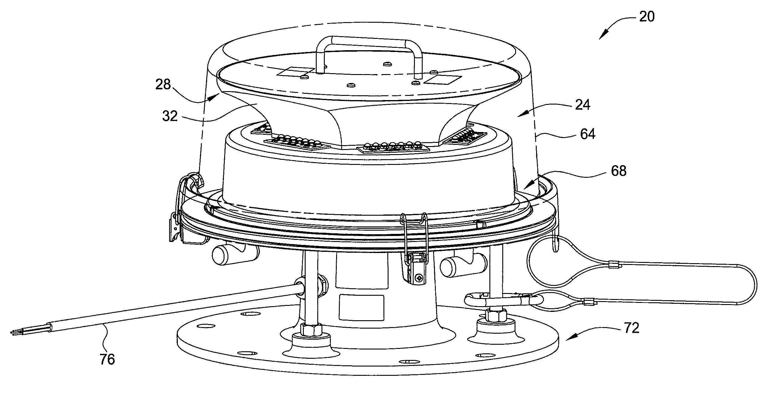
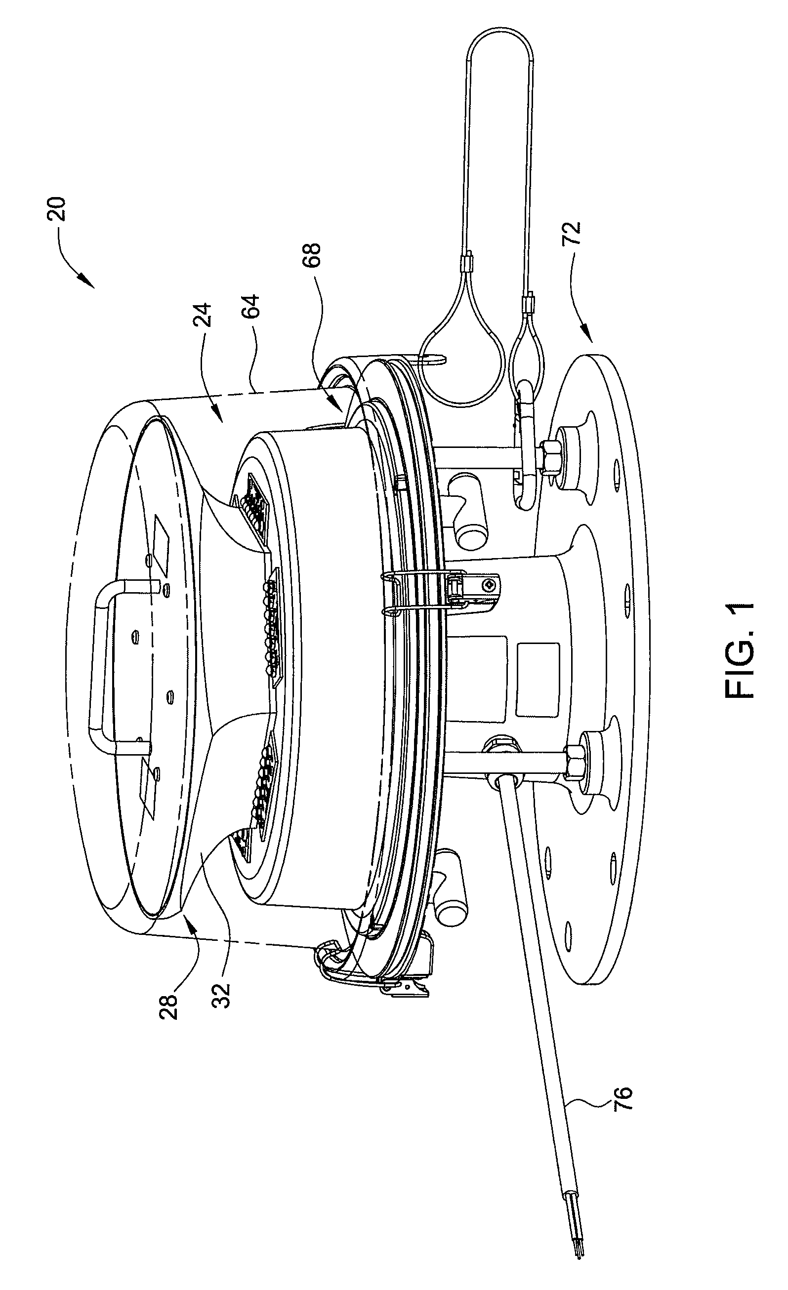
[0037]FIG. 1 depicts a perspective view of a beacon light 20 according to one embodiment of the present invention. The beacon light 20 comprises an LED reflector optic 24. In one embodiment, the beacon light 20 also comprises a shield 64, a pedestal 68, a base 72, an electrical connection 76 to the beacon light 20, and circuitry (not shown) to drive the beacon light 20. In one embodiment, the drive circuitry (not shown) is capable of strobing the LED reflector optic 24. The pedestal 68 supports the LED reflector optic 24, and the base 72 provides a means for attaching the beacon light 20 to a structure.

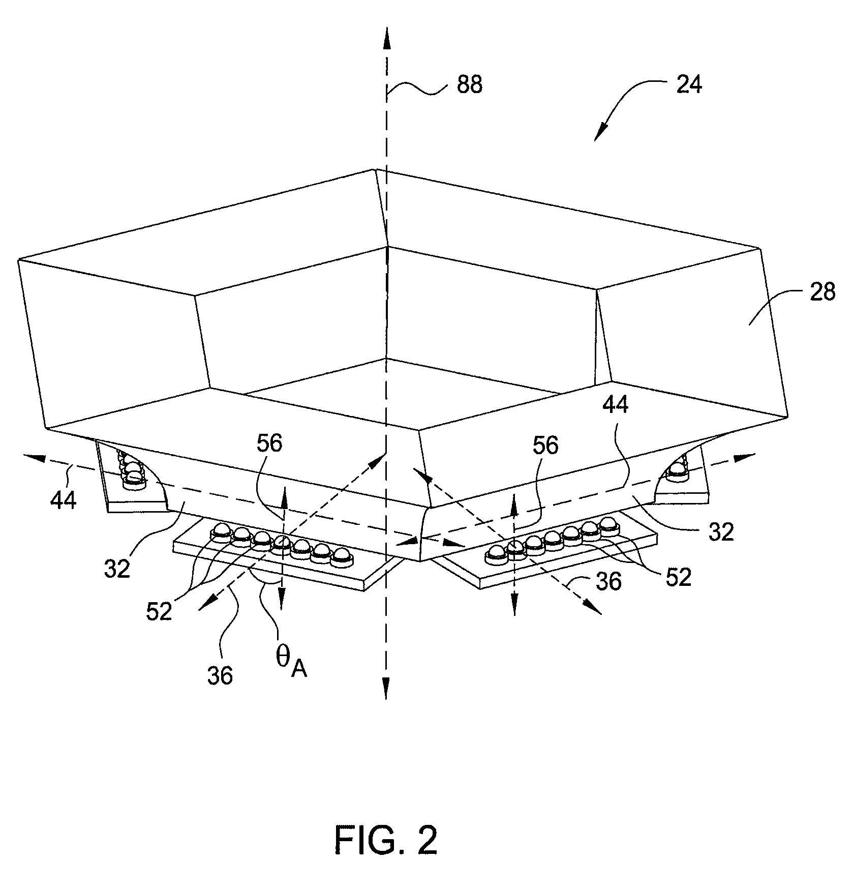
[0038]FIG. 2 depicts a perspective view of an embodiment of the LED reflector optic 24 according to the present invention. In one embodiment, the LED reflector optic 24 comprises a reflector 28 having a plurality of reflecting surfaces 32, i.e., a segmented reflector 28.

[0039]Each reflecting surface 32 comprises a cross-section 40 (as depicted in FIG. 8) which is projected along an as...


PUM


Abstract

The present invention is directed to a beacon light with a light emitting diode (LED) reflector optic. In one embodiment, the LED reflector optic includes a reflector having a plurality of reflecting surfaces and being associated with at least one optical axis, each reflecting surface including a curved cross-section and at least one LED positioned at a focal distance of a respective one of the plurality of reflecting surfaces.

Description

CROSS REFERENCE TO RELATED APPLICATIONS[0001]This application claims priority under 35 U.S.C. § 119(e) to U.S. provisional patent application Ser. No. 61 / 021,210, filed on Jan. 15, 2008, which is hereby incorporated by reference in its entirety.BACKGROUND OF THE INVENTION[0002]1. Field of the Invention[0003]The present invention generally relates to a light source, and more particularly to a light-emitting diode (LED)-based beacon light.[0004]2. Description of the Related Art[0005]A beacon light such as, for example, an aircraft obstruction light, can be used to mark an obstacle that may provide a hazard to aircraft navigation. Beacon lights are typically used on buildings, towers, and other structures taller than about 150 feet. Previous beacon lights generally exhibit relatively poor energy efficiency, which can prohibit the use of solar panels to power the beacon light. Previous beacon lights may also contribute to light pollution, i.e., direct light at angles undesirably above a...

Claims


Application Information

Patent Timeline
Patent Type & Authority Applications(United States)
IPC IPC(8): F21V1/00
CPCB64F1/20F21V7/0008F21V7/04F21K9/50F21W2111/06F21Y2101/02B64D2203/00F21V7/09F21Y2115/10F21K9/60
Inventor PECK, JOHN PATRICKLEIB, III, WILLIAM S.
Owner DIALIGHT CORP
Why Eureka
Try Eureka