Method and apparatus for a fluid delivery system with controlled fluid flow rate

a fluid flow rate and fluid technology, applied in the field of parenteral medical fluid delivery systems, can solve the problems of system change or reduction of fluid flow rate, affecting the ability of the system to administer the desired flow rate of a given fluid, and affecting the flow rate of fluid in the source,

Inactive Publication Date: 2009-09-03
BAXTER INT INC +1
View PDF9 Cites 45 Cited by
  • Summary
  • Abstract
  • Description
  • Claims
  • Application Information

AI Technical Summary

Benefits of technology

[0009]In one aspect of the present invention, a medical fluid delivery system may be provided, which may comprise a fluid flow path for communication between a fluid source and a patient. A flow valve may be operatively associated with the fluid flow path. Such valve may be movable between a first position, which allows fluid flow through the path, and a second position, which limits fluid flow through the path. A control module may be operatively associated with the valve to move the valve between the first and second positions in response to a measured actual fluid flow rate in the fluid flow path.

Problems solved by technology

However, certain prior art systems experience a change or reduction in the fluid flow rate as the amount of fluid in the source, e.g., a bag or other container, is exhausted.
Also, infusion systems are often used with fluids of differing viscosity, which further complicates the ability of the system to administer the desired flow rate of a given fluid.
However, this may be inconvenient or subject to error in the event viscosity is not known or available to user or, even if known, may not be accurate due to changes in temperature of the fluid in the system.
Also, prior art ambulatory infusion systems may not provide monitoring and adjustment of the actual flow rate during a particular fluid delivery therapy.
For example, such systems generally may not allow the actual flow rate to be adjusted during a fluid delivery therapy as desired for a particular patient.
Prior art ambulatory infusion systems further typically limit the ability of the patient to change or vary the flow rate of fluid delivery during a fluid delivery therapy.
For example, a patient may need to slow or stop fluid delivery if the patient has an adverse reaction to the delivery fluid.

Method used


Image

  • Method and apparatus for a fluid delivery system with controlled fluid flow rate
  • Method and apparatus for a fluid delivery system with controlled fluid flow rate
  • Method and apparatus for a fluid delivery system with controlled fluid flow rate

Examples


Embodiment Construction

[0060]While the present invention will be described in terms of certain preferred or alternative embodiments, it is contemplated that the present invention may employ various structures, modifications and alternatives and that the scope of the invention is as set forth in the attached claims.

System Overview

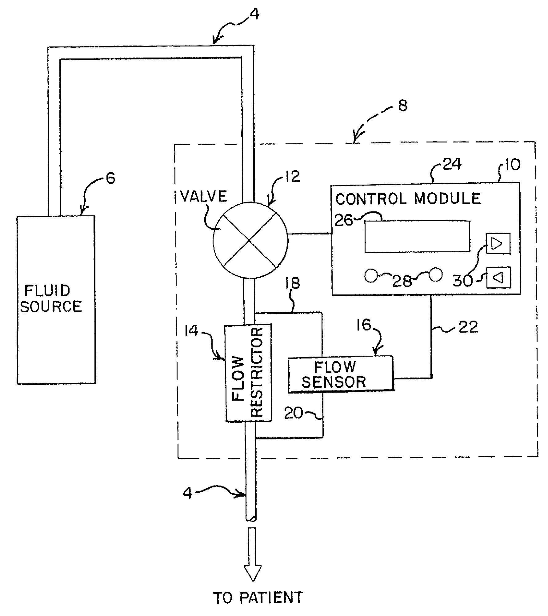
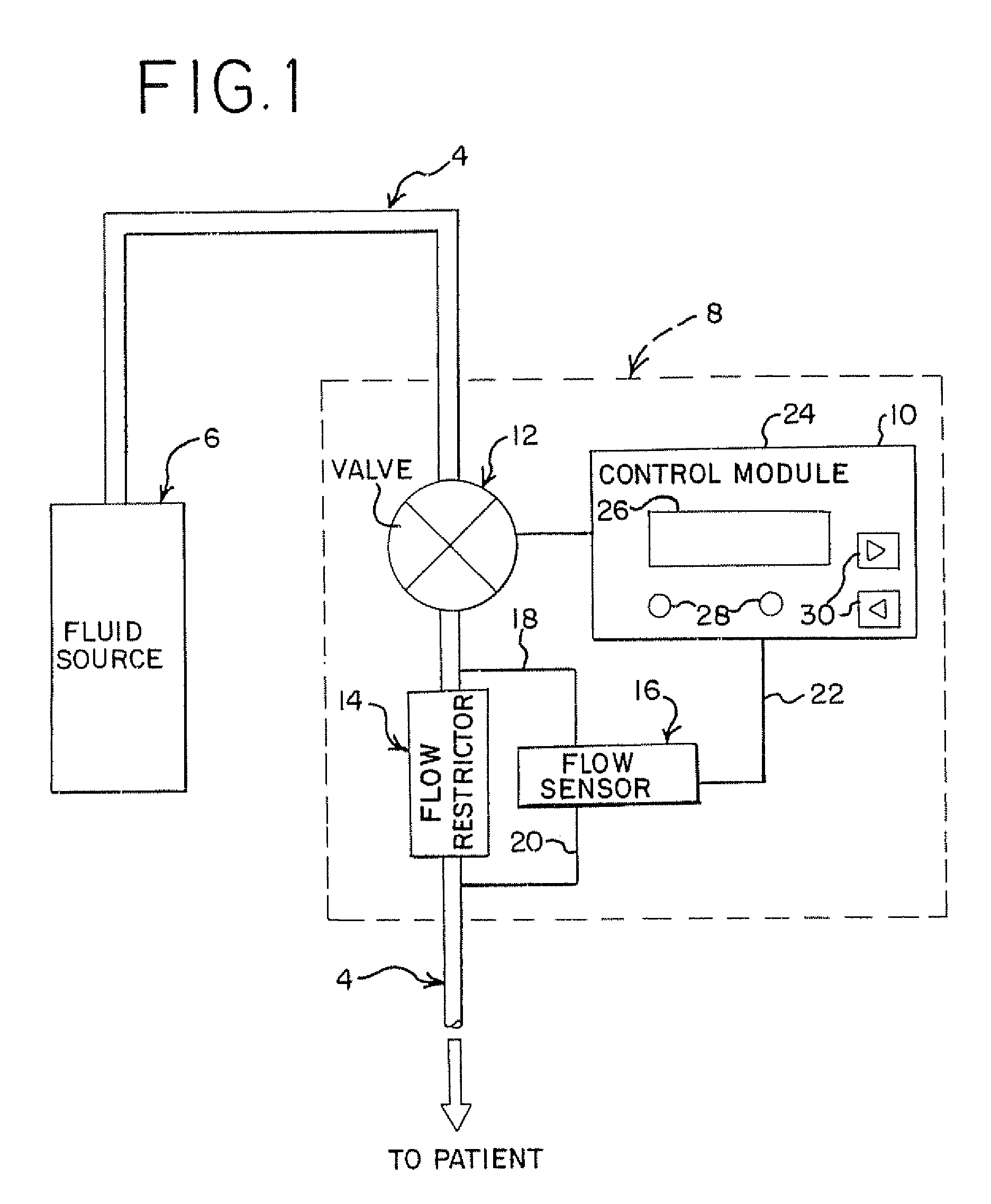
[0061]In accordance with one embodiment of the present invention, FIG. 1 is a schematic representation of a fluid delivery system embodying the present invention, preferably an ambulatory fluid delivery system, generally indicated at 2, for delivering a medical fluid to a patient. It is noted that the fluid delivery system in FIG. 1 is shown schematically to illustrate certain broader aspects of the present invention, not limited to particular structures illustrated in more detailed figures. In FIG. 1, the system 2 includes a fluid flow path, generally indicated at 4, which communicates between a fluid source, generally indicated at 6, and the patient, via a connector and a cathet...


PUM


Abstract

The present invention includes systems and methods for medical fluid delivery. Such system may comprise a fluid flow path for communication between a fluid source and a patient. A flow valve is operatively associated with the path and movable between a first position, which allows fluid flow through the path, and a second position, which limits fluid flow through the path. A control module is operatively associated with the valve to move the valve between the first and second positions in response to a measured actual fluid flow rate in the path. Such method may comprise flowing a fluid through a fluid flow path between a portable fluid source and a patient; determining an actual fluid flow rate through the path; and changing the actual fluid flow rate in response to a difference between the actual fluid flow rate and a desired fluid flow rate. Such method may further include a plurality of settings for a desired flow rate according to a sensed pain level of the patient.

Description

BACKGROUND[0001]This invention generally relates to a parenteral medical fluid delivery system and its method of use.[0002]It is common to parenterally administer or infuse medical liquids of various types to patients for therapeutic treatment, pain management and / or other reasons. The liquid or fluid may include a pharmaceutically active agent or drug, saline, nutritional fluid or other liquids. Such an infusion system may deliver fluid to the patient through a disposable flow circuit over a selected time period according to a programmed flow rate, or flow profile. While it is common for such infusion to be performed in a hospital environment where the patient is largely confined to a bed, if the infusion occurs over a long time period, it may be more convenient for the infusion be performed while the patient remains ambulatory.[0003]In ambulatory as well as other medical fluid infusion systems, it is desirable for the flow rate to be accurate over the entire infusion period for ad...

Claims


Application Information

Patent Timeline
Patent Type & Authority Applications(United States)
IPC IPC(8): A61M5/168
CPCA61M5/16877A61M5/1723A61M2205/502A61M2205/50A61M2005/1405
Inventor WANG, JONG H.DESAI, SIDDHARTH B.CAPDEVILA, XAVIER
Owner BAXTER INT INC
Why Eureka
Try Eureka