Light source adjusting and controlling switch device

a switch device and light source technology, applied in the direction of keyboard-like device coding, pulse technique, coding, etc., can solve the problems of poor contact, affecting lighting adjustment, and the inability to adjust the brightness of most conventional lamps, so as to eliminate the aforesaid drawbacks

Inactive Publication Date: 2009-09-17
CHEN CHING NAN
View PDF6 Cites 43 Cited by
  • Summary
  • Abstract
  • Description
  • Claims
  • Application Information

AI Technical Summary

Benefits of technology

[0006]The present invention has been accomplished to provide a light source adjusting and controlling switch device that eliminates the aforesaid drawbacks. According to one aspect of the present invention, the light source adjusting and controlling switch device is installed in a lamp, and comprises a control circuit inside and a capacitance-type touch pad on the surface for allowing a user to touch with a finger. The capacitance-type touch pad has a plurality of detection elements electrically connected to a touch sensor of the control circuit. When the user touches the capacitance-type touch pad with a finger, a capacitance will be produced on the capacitance-type touch pad, and the plurality of detection elements will sense the position of the finger to produce corresponding signals. After the touch sensor receives the signal, a microprocessor of the control circuit will operate immediately to switch on / off, brightness and colors to a connected light emitting device according to the signal. Thus, the design does not need any extra special tools and can be operated by only the touch of a finger. Furthermore, the design can execute multi-point movement and operation simultaneously and immediately, solving the difficult recognition in the prior art.

Problems solved by technology

However, the brightness in most conventional lamps cannot be adjusted and only switched on or off.
However, over periods of time, the contact spring inside the sectional switch will be weakened and cause poor contact; which in turn affects lighting adjustments.
Brightness of the lamp is controlled by sections; therefore, other brightness changes cannot be adjusted precisely.

Method used


Image

  • Light source adjusting and controlling switch device
  • Light source adjusting and controlling switch device
  • Light source adjusting and controlling switch device

Examples


Embodiment Construction

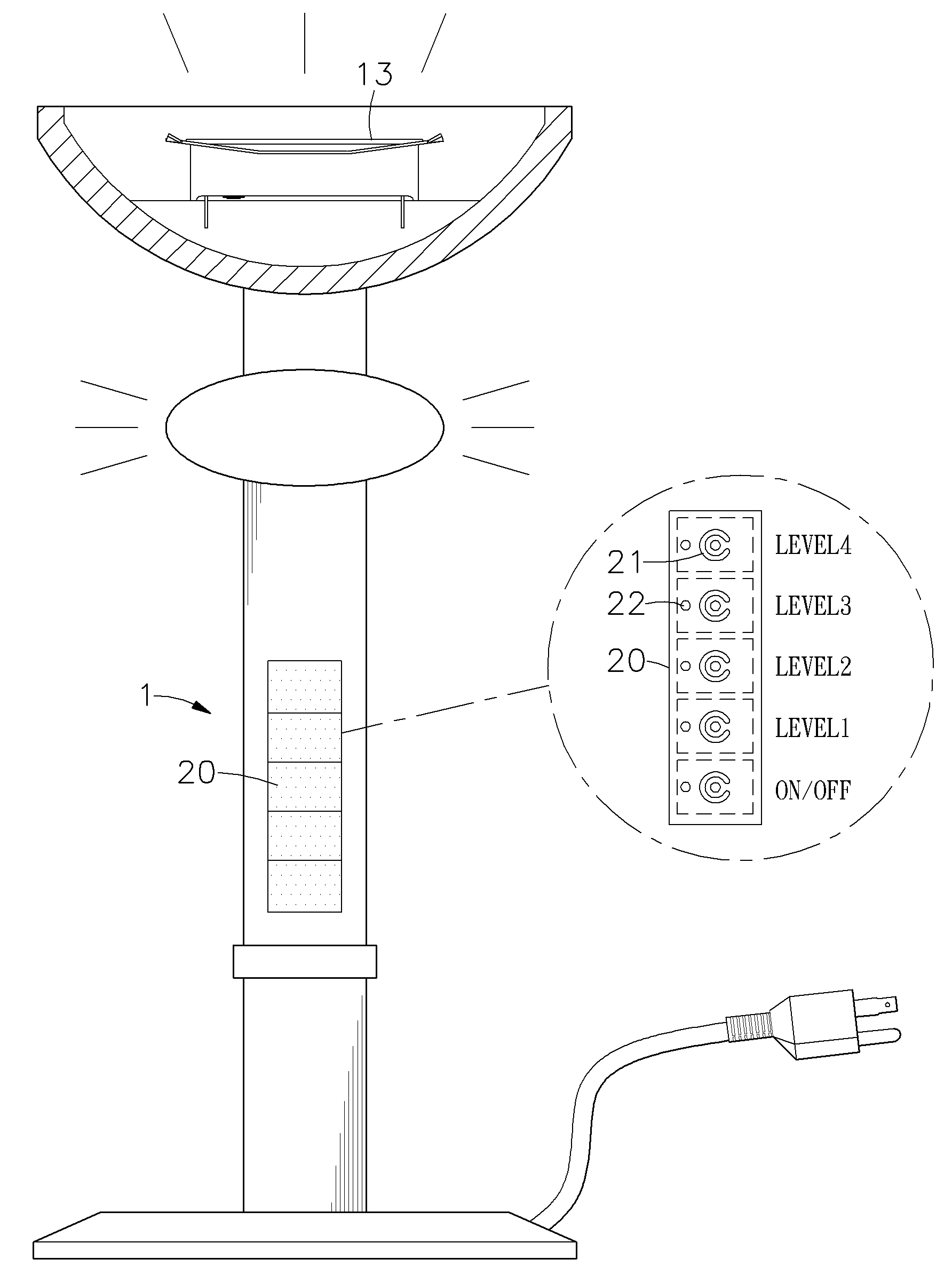
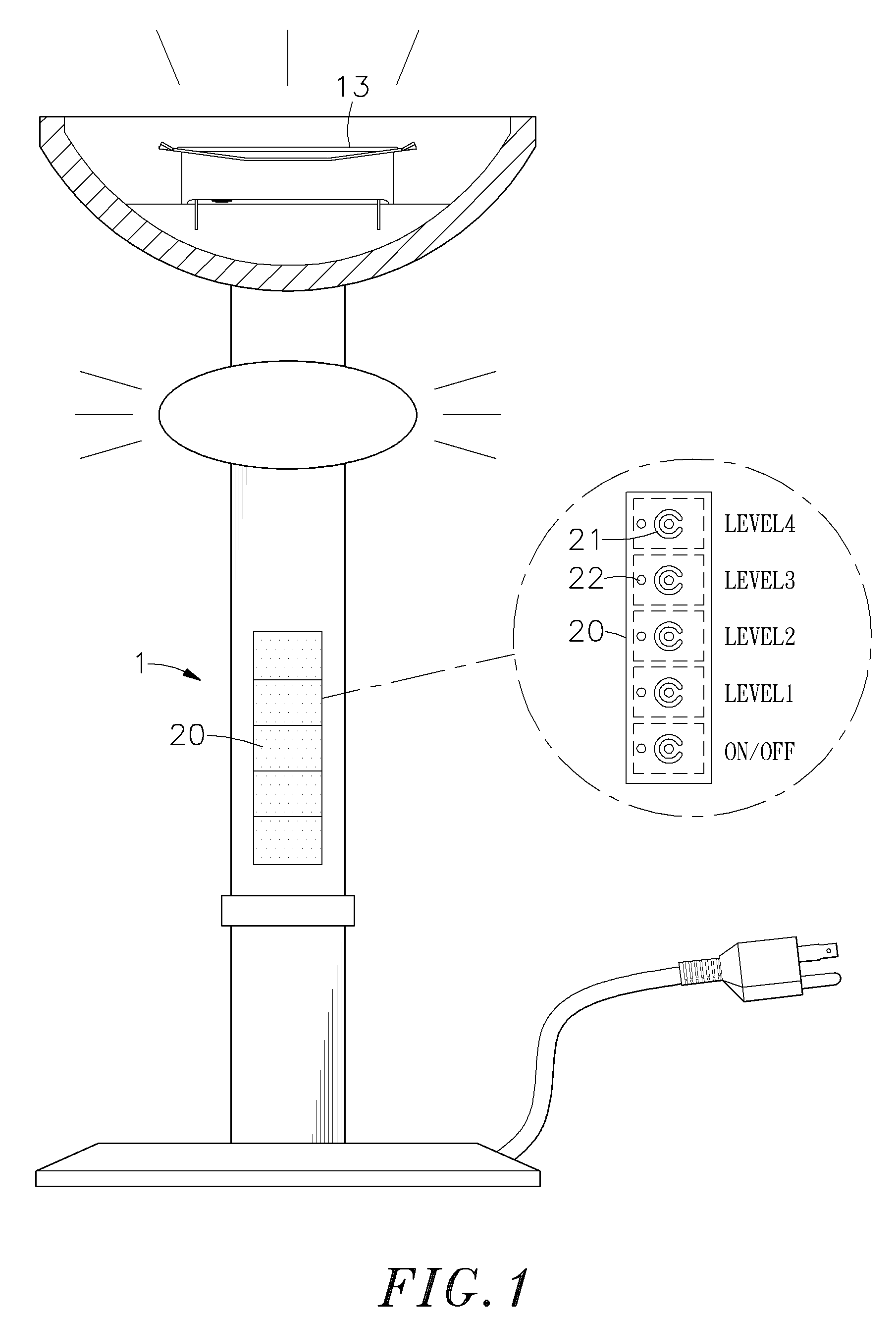
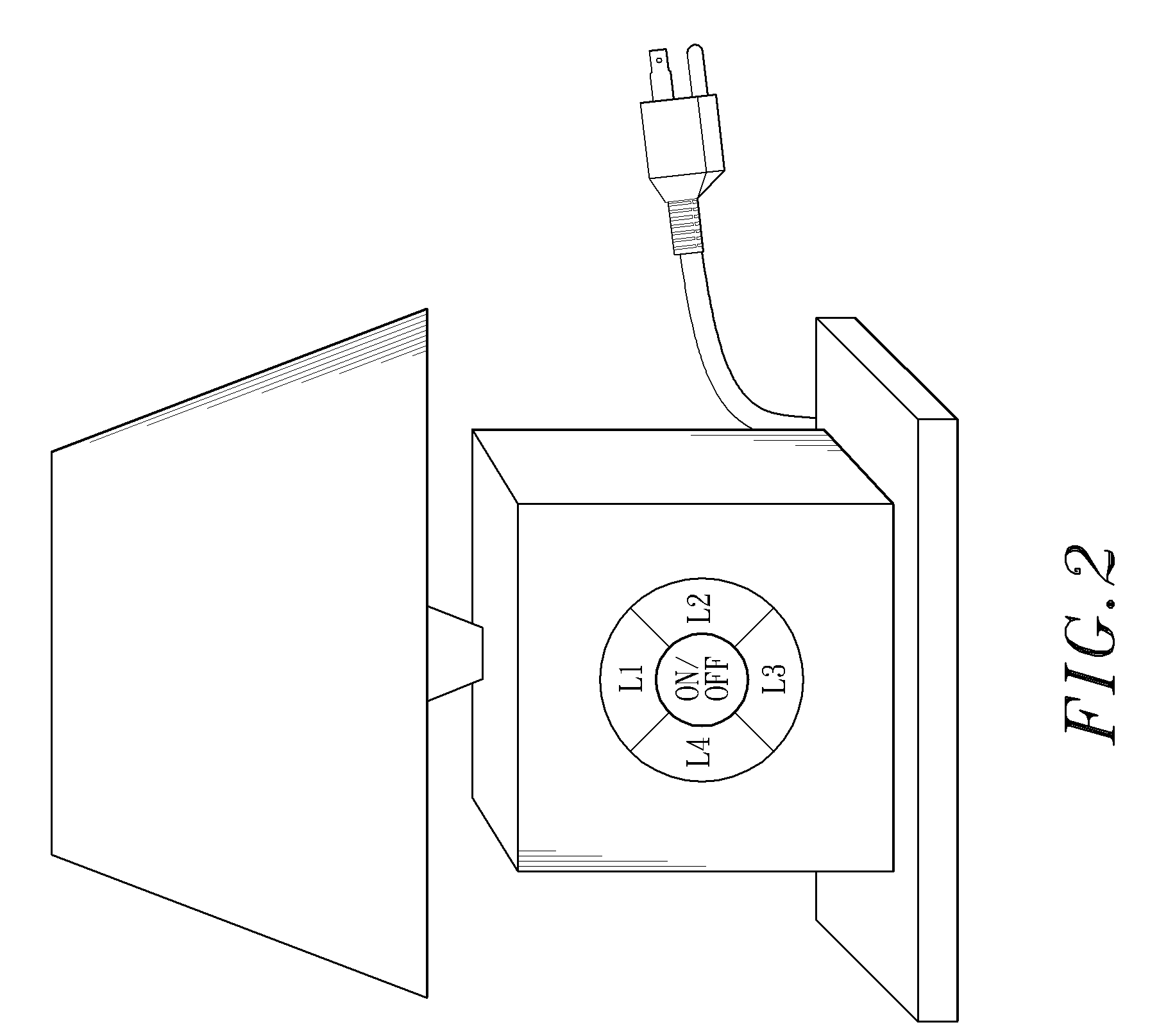
[0031]FIGS. 1˜6 show the first and second preferred embodiments of the present invention. In the two embodiments, a light source adjusting and controlling switch device is installed in a lamp 1, having a control circuit 10 inside, and a capacitance-type touch pad 20 on the surface thereof. The control circuit 10 comprises a microprocessor 11, a touch sensor 12, a light emitting device 13 and a power supply device 14. Furthermore, the capacitance-type touch pad 20 comprises a plurality of detection elements 21 and a plurality of light indicator 22 corresponding to the detection elements 21. The detection elements 21 and the light indicators 22 of the capacitance-type touch pad 20 are electrically connected with the touch sensor 12 and the microprocessor 11 of the control circuit 10 inside the lamp 1 respectively.

[0032]When in use, the power supply device 14 is connected to an external power supply 30, namely AC110V˜AC220V, and AC shall be transformed into DC and sent to the control c...


PUM


Abstract

The present invention provides a light source adjusting and controlling switch device, which comprises a control circuit, and a capacitance-type touch pad mounted on the surface of a lamp and connected to the control circuit. The capacitance-type touch pad has a plurality detection element and is electrically connected with a touch sensor of the control circuit. When a user touches the capacitance-type touch pad with a finger, a capacitance will be produced on the capacitance-type touch pad, and the plurality of detection element can sense the position of the finger and produce a corresponding capacitance variable amount signal. After the touch sensor receives the signal, a microprocessor of the control circuit will operate the switch on / off, the brightness and color to a connected light emitting device immediately.

Description

[0001]This application claims the priority benefit of Taiwan patent application number 097204245 filed on Mar. 12, 2008.BACKGROUND OF THE INVENTION[0002]1. Field of the Invention[0003]The present invention relates generally to a light source adjusting and controlling a switch device, which uses a capacitance-type touch pad to switch the brightness of light sources or different colors.[0004]2. Description of the Related Art[0005]Conventional lamps used in rooms must be adjusted in brightness according to different conditions. For example, the brightness of a lamp will be turned down when people exit a room or sleep, in order to save electrical power; while maintaining enough light for vision. However, the brightness in most conventional lamps cannot be adjusted and only switched on or off. Some conventional lamps use the sectional switch to control the brightness. However, over periods of time, the contact spring inside the sectional switch will be weakened and cause poor contact; wh...

Claims


Application Information

Patent Timeline
Patent Type & Authority Applications(United States)
IPC IPC(8): H03K17/94
CPCH03K17/18H03K17/962H05B33/0863H05B33/0803H03K2217/960785H05B45/20H05B45/00
Inventor CHEN, CHING-NAN
Owner CHEN CHING NAN
Why Eureka
Try Eureka