System and Method for Regulating Bandwidth in a Multicast Video Transmission System

a multi-cast video and bandwidth regulation technology, applied in the field of multi-cast video transmission system bandwidth regulation system, can solve the problems of missing or corrupted information retransmission, and the possibility of doing more harm than good with a retransmission protocol

Active Publication Date: 2009-09-24
VERTIV IT SYST INC
View PDF22 Cites 17 Cited by
  • Summary
  • Abstract
  • Description
  • Claims
  • Application Information

AI Technical Summary

Problems solved by technology

As transmission errors occur in such a configuration, retransmission of missing or corrupted information is required in order to keep the displays of the receivers in synchronization with the transmitter.
However, it is possible to do more harm than good with a retransmission protocol.

Method used


Image

  • System and Method for Regulating Bandwidth in a Multicast Video Transmission System
  • System and Method for Regulating Bandwidth in a Multicast Video Transmission System
  • System and Method for Regulating Bandwidth in a Multicast Video Transmission System

Examples


Embodiment Construction

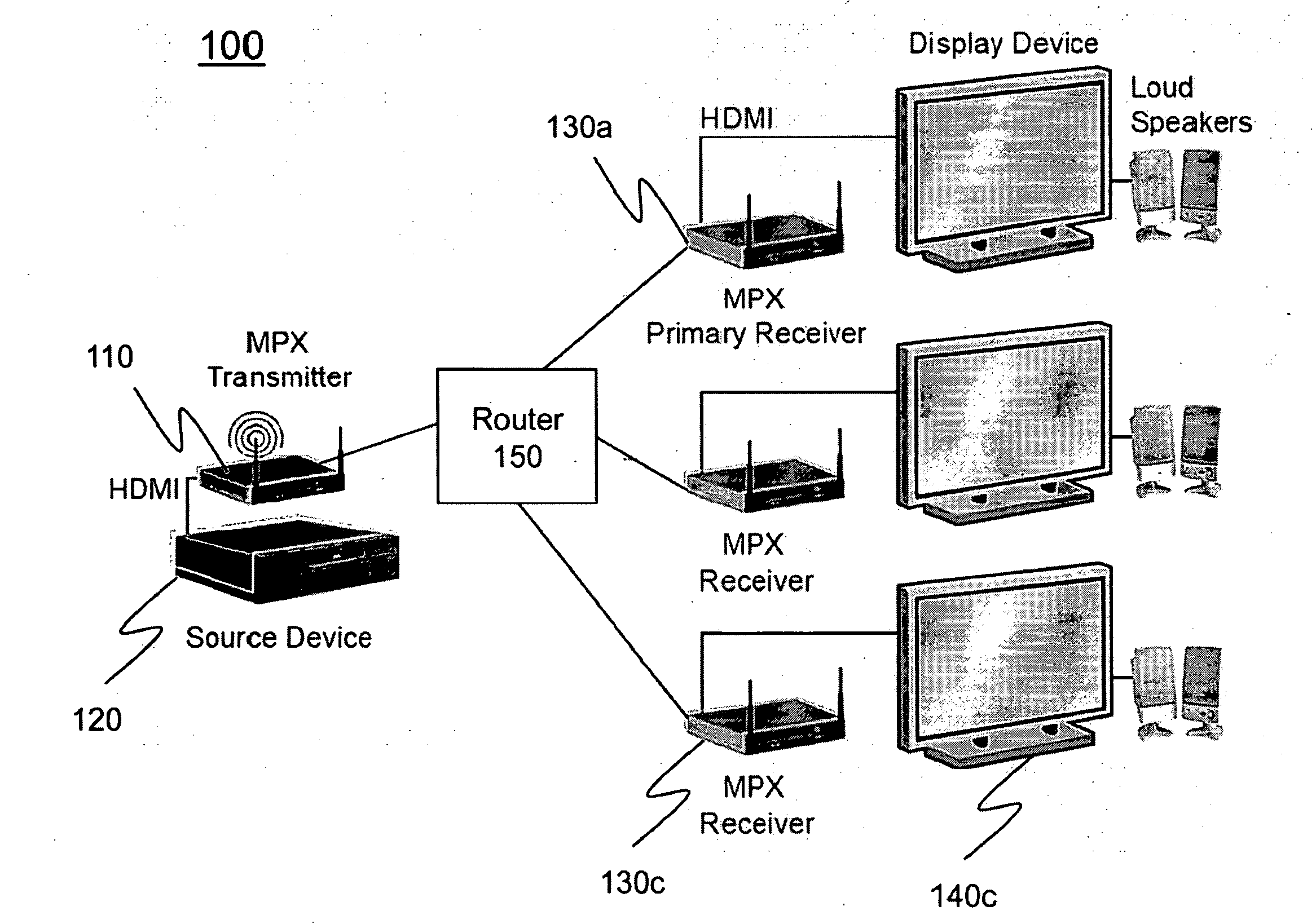
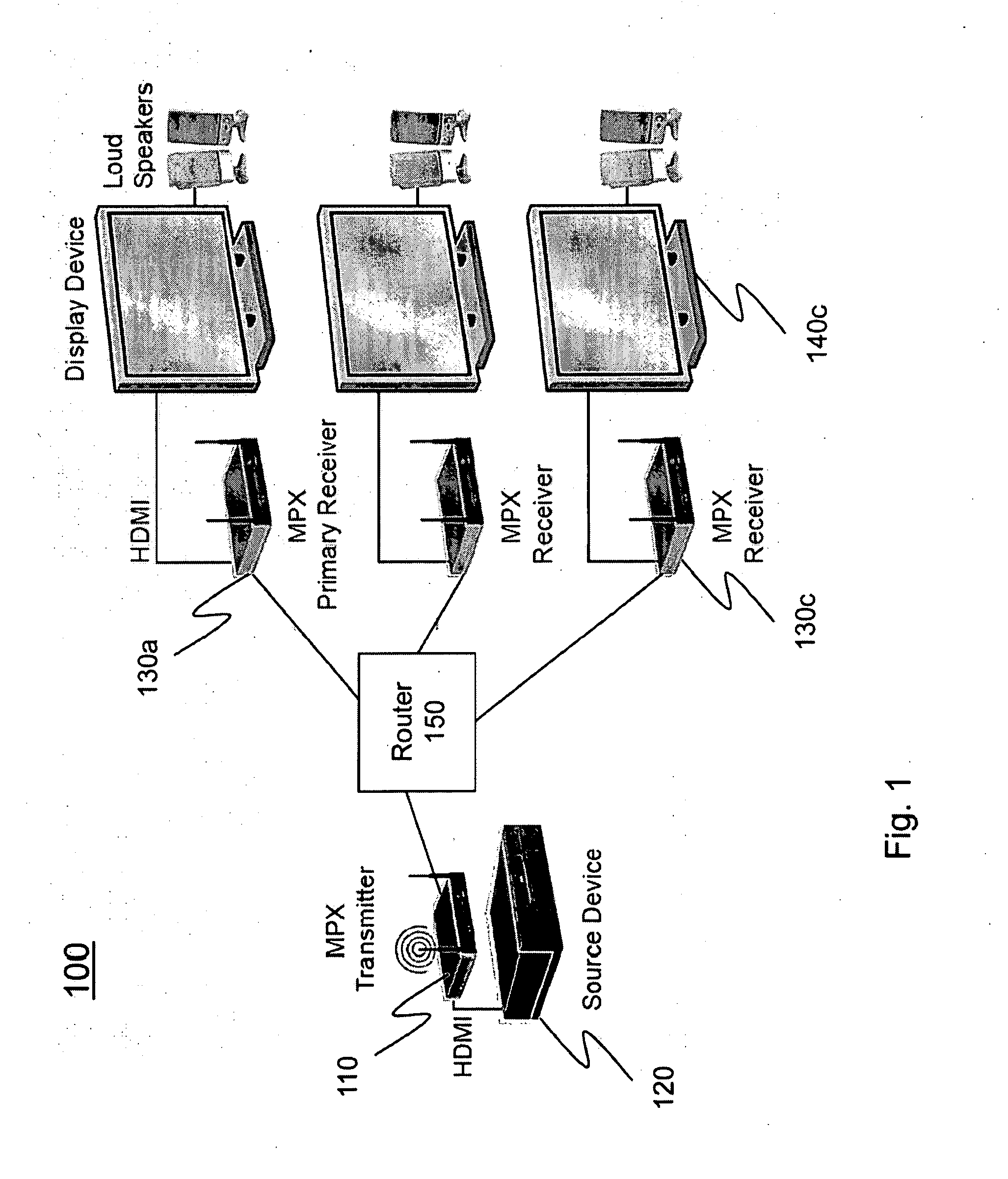
[0014]Turning to FIG. 1, a multi-display system 100 includes a transmitter 110 (at an originating end) that receives audio and / or video from an audio / video source 120 (e.g., a cable / satellite set-top box, a computer, a DVD player (either original definition or high definition), a game console, a CD player or any other electronics device) and converts the audio and / or video signal (hereinafter AV signal) to a digitized, packetized form. (In configurations in which a transmitter receives video already in digital form, the transmitter need not digitize the video but only packetize it.) The transmitter 110 then forwards (e.g., using at least one wireless packet-switched network) the converted AV signal on to plural receivers 130a-130c which convert the digital AV signals back to their native form and output them to display devices connected to AV connectors (260 of FIG. 3) via AV cables. As would be appreciated by those of ordinary skill in the art, the number of receivers 130 may be ot...


PUM


Abstract

A video transmitter can adaptively alter its transmission rate to plural receivers which receive video via multicast transmission. While the transmitter is initially in the “no tuning state,” the need for a video tune-up state change can be determined by calculating if the current generated A / V retry transmission rate is greater than the video tune-up start threshold and if it was triggered more than the video tune-up interval ago. If so, then the state can be set to “tuning up” and the retransmission rate can be increased by the video tune-up step, as shown in FIG. 7. However, if the state is set to “tuning up” and it is determined that the current generated A / V retry transmission rate is greater than the video tune-up stop threshold, then “tuning-up” is no longer required, and the state is set such that “tuning up” is no longer true such that the state returns to the “no tuning” state. Likewise, the need for a video tune-down state change can be determined by calculating if the current generated A / V retry transmission rate is greater than the video tune-down start threshold and if it was triggered more than the video tune-down interval ago. If so, then the state can be set to “tuning down” and the retransmission rate can be increased by the video tune-down step. However, if the state is set to “tuning down” and it is determined that the current generated A / V retry transmission rate is less than the video tune-down stop threshold, then “tuning-down” is no longer required, and the state is set such that “tuning down” is no longer true and the state returns to the “no tuning” state.

Description

CROSS REFERENCE TO RELATED APPLICATIONS[0001]The present application is related to and claims priority to U.S. Provisional Patent Application 60 / 960,913, filed Oct. 19, 2007, the contents of which are incorporated herein by reference. The present application is further related to U.S. Non-Provisional and Provisional patent application Ser. Nos. 11 / 896,970 and 60 / 842,706, filed Sep. 7, 2007 and Sep. 7, 2006, respectively. The contents of those applications are also incorporated herein by reference.FIELD OF INVENTION[0002]The present invention is directed to a system and method for communicating between a transmitter and its corresponding group of receivers in a multicast communications system. In one such configuration, a set of quality of service thresholds are configurable in a transmitter and its receivers to compensate for retransmission overhead and congestion caused by retransmission.DISCUSSION OF THE BACKGROUND[0003]Keyboard, video and mouse (KVM) switches are known and used i...

Claims


Application Information

Patent Timeline
Patent Type & Authority Applications(United States)
IPC IPC(8): H04N7/18H04N7/16H04L12/26
CPCH04L12/2807H04L12/2838H04L29/12226H04L29/12283H04L61/2015H04L61/2061H04N21/64322H04N21/4108H04N21/4122H04N21/43615H04N21/43632H04N21/43637H04N21/6405H04L2012/2849H04L61/5014H04L61/5061
Inventor LO, LAWRENCE
Owner VERTIV IT SYST INC
Why Eureka
Try Eureka