Surveillance Camera System

a camera system and surveillance technology, applied in the field of surveillance camera systems, can solve the problems of time-consuming, difficult installation, maintenance and repair of systems, and achieve the effect of minimal maintenance, easy installation, upgrading and maintaining

Inactive Publication Date: 2008-03-06
VICON INDS
View PDF15 Cites 105 Cited by
  • Summary
  • Abstract
  • Description
  • Claims
  • Application Information

AI Technical Summary

Benefits of technology

[0005] The present invention overcomes the disadvantages of the prior art by providing a surveillance camera system which is easy to install, upgrade and maintain, will accept any appropriate surveillance camera and video transmission option and is programmed to operate with a multitude of competitive communication protocols with minimal servicing required.

Problems solved by technology

A disadvantage of the known surveillance camera systems relates to the difficulty of installing, updating and servicing the systems.
More specifically, the prior art surveillance camera systems have been complex electromechanical structures and when servicing was required, it would usually require removal and reconfiguration of the entire structure which was not always an easy, time-effective procedure.

Method used


Image

  • Surveillance Camera System
  • Surveillance Camera System
  • Surveillance Camera System

Examples


Embodiment Construction

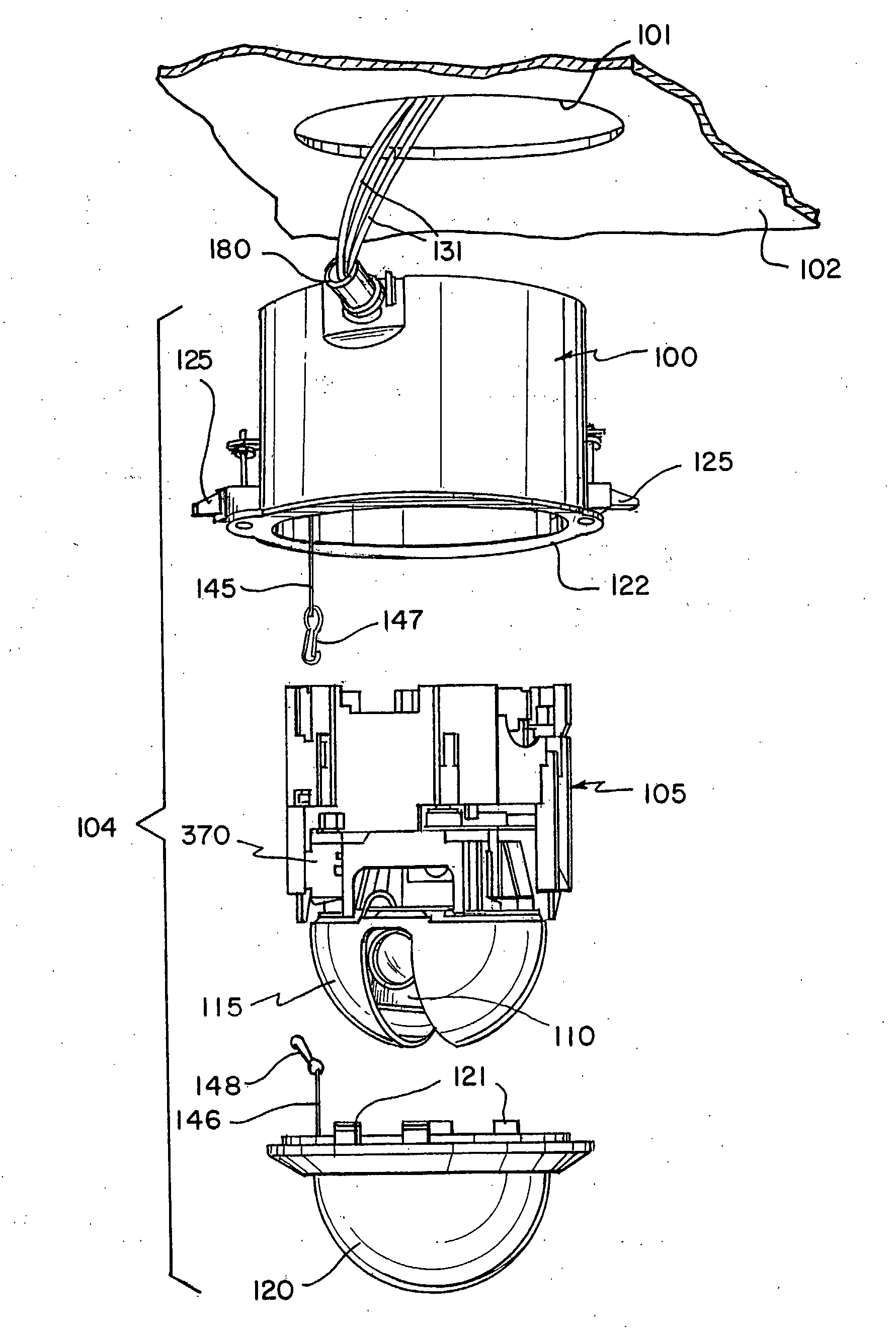
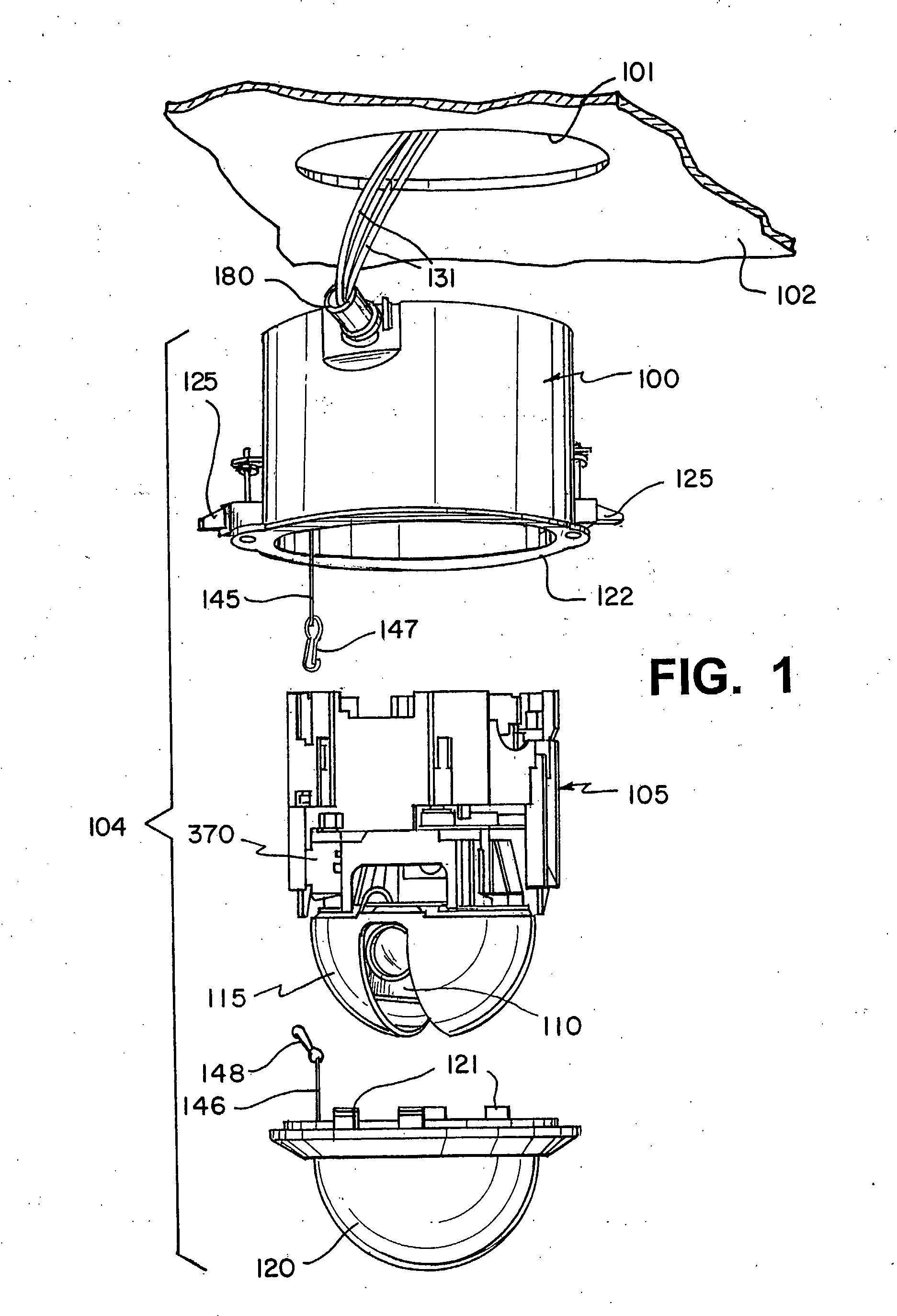
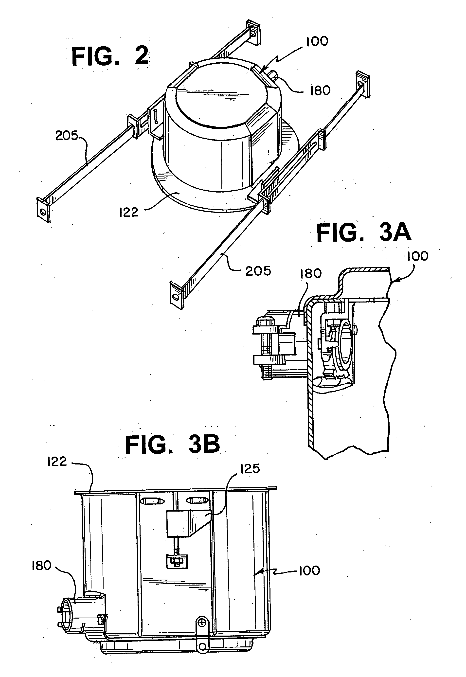
[0037] Referring to FIG. 1, a surveillance camera system 104 according to the present invention comprises housing 100, camera drive 105, video camera 110, shroud 115 and dome 120. Housing 100 encloses the components of the surveillance camera system 104 above the ceiling. Preferably, surveillance camera system 104 is installed into an orifice 101 of an existing ceiling 102 in the area to be monitored and rests on the inner ceiling surface occupying the space between ceiling 102 and the upper building frame (not shown). During installation, housing 100 is lifted up through orifice 101 and a pair of locking flippers 125 are secured against ceiling 102 thereby securing housing 100 to ceiling 102. If necessary, additional support for housing 100, other than the ceiling 102 material, can be provided through the use of optional support rails 205, as shown in FIG. 2. Support rails 205 can be formed at one end to be attached to housing 100 and at the other end to be attached onto an inner s...


PUM


Abstract

A surveillance camera system capable of accepting any appropriate surveillance camera and video transmission option and is programmed to operate with a multitude of competitive communication protocols with minimal servicing required. The system can quickly convert and/or update the camera system to be able to transmit video data over coaxial cable, unshielded twisted-pair (UTP), fiber optics or IP. A conversion from UTP to IP can convert the camera assembly into a network server for TCP/IP communication enabling the camera to be controlled locally or from any location over the internet using any installed network video protocol. The camera assembly with the ability to quickly configure the communication video interface via switch selectable on-board communication protocols.

Description

FIELD OF THE INVENTION [0001] The present invention relates to a surveillance camera system and, more particularly, to surveillance cameras for use with closed-circuit television systems, such as for indoor or outdoor store security, building security, and any other security or monitoring applications. BACKGROUND OF THE INVENTION [0002] Surveillance camera systems are commonly used to monitor various areas, such as cashier windows, store parking lots or gambling tables at a casino. Typically, an operator of such a surveillance system is located at a central location from which he controls one or more camera units that are remotely positioned throughout the area to be monitored. The remote units are often mounted in hemispherical domes that are suspended from the ceiling of the monitored area. By using a keyboard console, the operator selects images from the remote cameras to be displayed on one or more video monitors. Some systems include a joy stick on the control console to permit...

Claims


Application Information

Patent Timeline
Patent Type & Authority Applications(United States)
IPC IPC(8): H04N7/18
CPCG03B37/02G08B13/19619G08B13/1963H04N5/2252G08B13/19656G08B13/19686G08B13/19632H04N23/51
Inventor MARS, JEFFSAVETTIERE, JOSEPHREN, XIANPINGFAKELMANN, MARKPSHTISSKY, YACOVRANDMAC, REIN S.
Owner VICON INDS
Why Eureka
Try Eureka