Base station apparatus and channel allocation method

a channel allocation and base station technology, applied in electrical equipment, telephonic communication, substation equipment, etc., can solve the problems of deteriorating signal reception quality and terms of frequency utilization efficiency, and achieve the effect of improving frequency utilization efficiency

Inactive Publication Date: 2009-10-01
KYOCERA CORP
View PDF7 Cites 28 Cited by
  • Summary
  • Abstract
  • Description
  • Claims
  • Application Information

AI Technical Summary

Benefits of technology

[0012]The present invention has been made in view of the above-mentioned problem of prior art, and an object of the present invention is therefore to provide a base station apparatus and a channel allocation method that improve frequency utilization efficiency, for example. Additional features will become readily apparent by reference to the following detailed description when taken in conjunction with the accompanying drawings.

Problems solved by technology

This makes it difficult for the base station 70 to correctly demodulate a signal transmitted on the subcarrier (4), and the signal reception quality is deteriorated.
This is a problem in terms of frequency utilization efficiency.

Method used


Image

  • Base station apparatus and channel allocation method
  • Base station apparatus and channel allocation method
  • Base station apparatus and channel allocation method

Examples


Embodiment Construction

[0038]The following description is presented to enable a person of ordinary skill in the art to make and use the invention. Descriptions of specific devices, techniques, and applications are provided only as examples. Various modifications to the examples described herein will be readily apparent to those of ordinary skill in the art, and the general principles defined herein may be applied to other examples and applications without departing from the spirit and scope of the invention. Thus, the present invention is not intended to be limited to the examples described herein and shown, but is to be accorded the scope consistent with the claims.

[0039]The word “exemplary” is used herein to mean “serving as an example or illustration.” Any aspect or design described herein as “exemplary” is not necessarily to be construed as preferred or advantageous over other aspects or designs.

[0040]Reference will now be made in detail to aspects of the subject technology, examples of which are illu...


PUM


Abstract

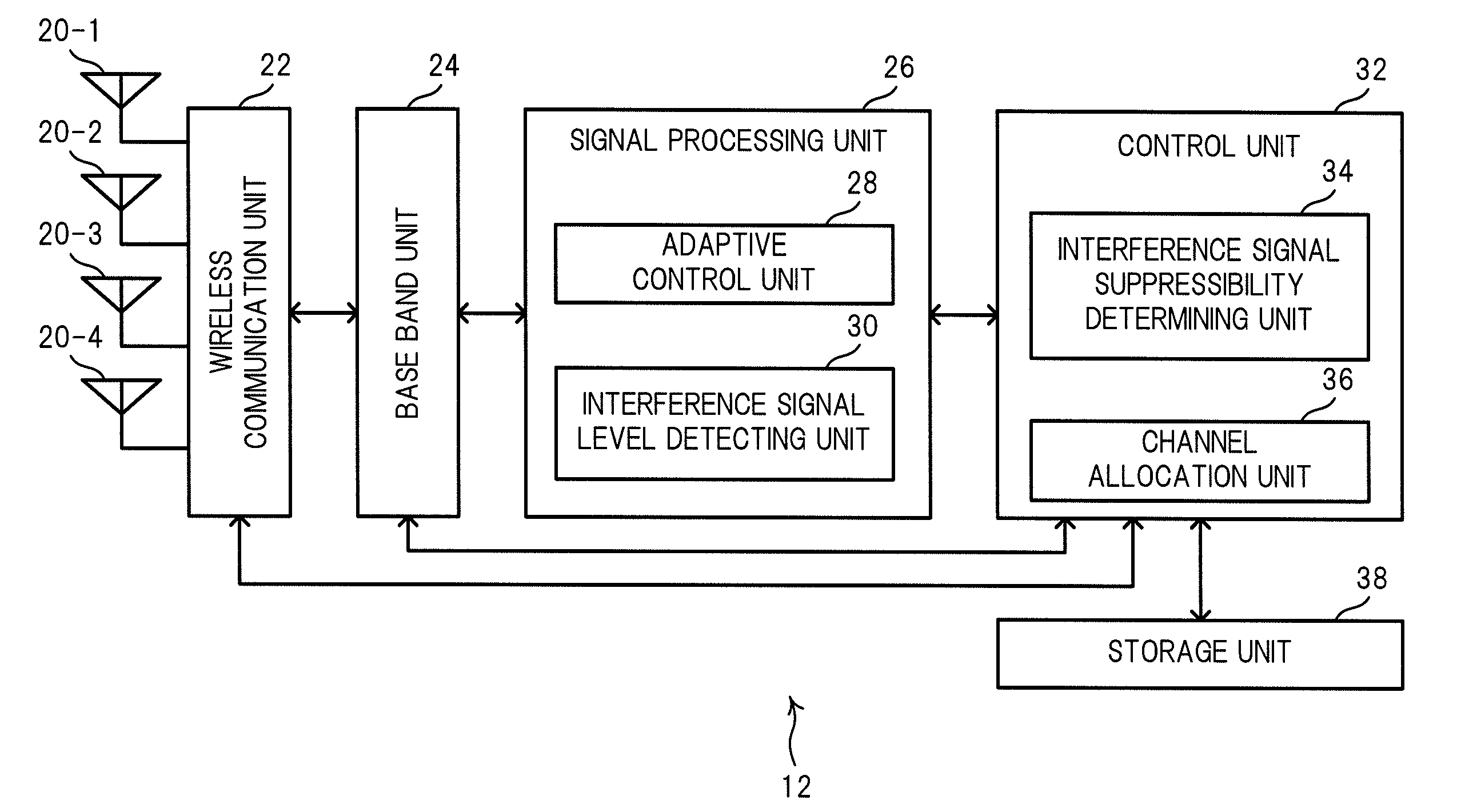
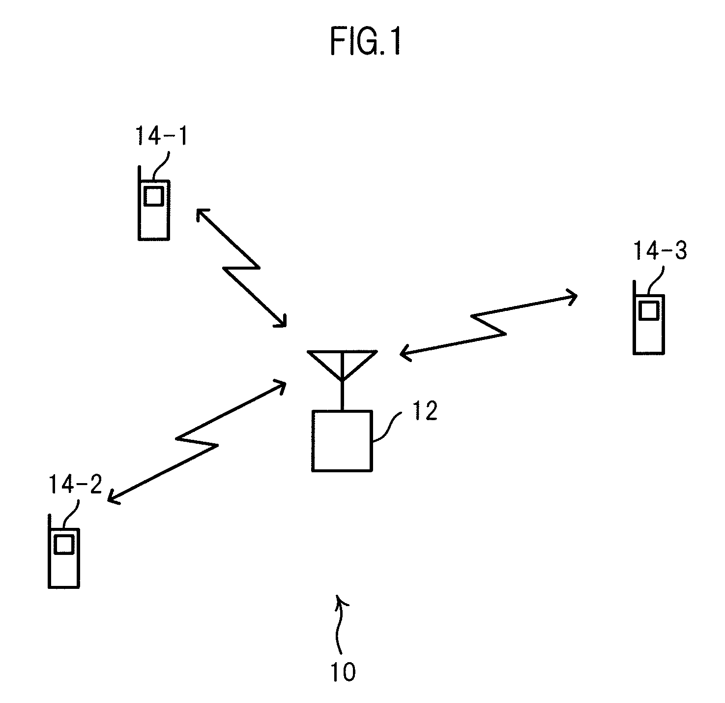
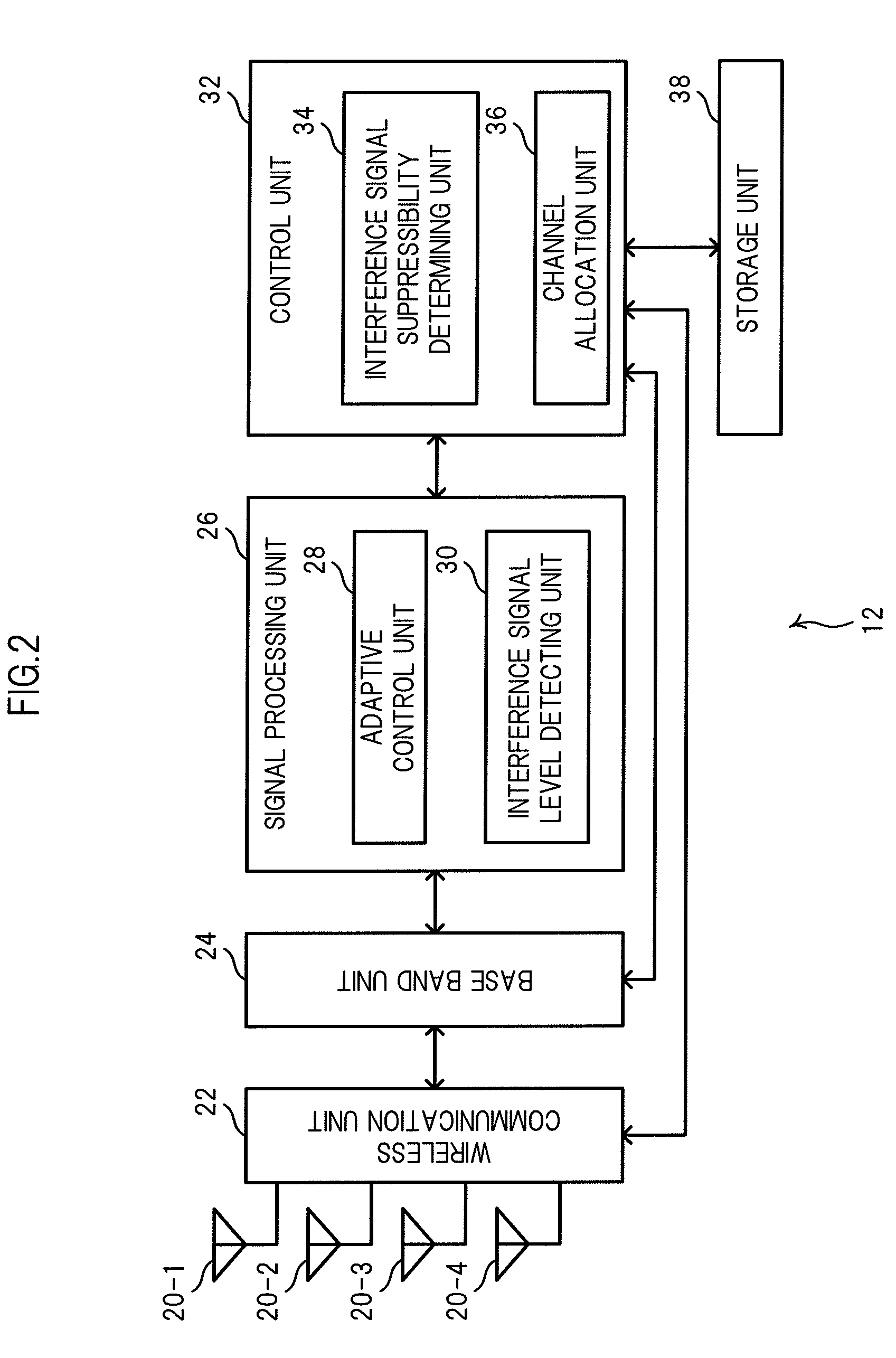
A base station includes an adaptive control unit for obtaining weights (w1′ to w4′) of antenna elements indicating an arrival direction of an interference signal detected on a radio channel that is not being used for communication, and weights (w1 to w4) indicating an arrival direction of a desired signal arriving from a mobile station. The base station further includes an interference signal suppressibility determining unit for determining, based on the weights (w1 to w4) and the weights (w1′ to w4′), whether or not it is possible to form a direction pattern that directs a main beam toward the arrival direction of the desired signal and directs a null toward the arrival direction of the interference signal; and a channel allocation unit for determining, based on a result of the determination, whether to allocate the mobile station the radio channel on which the interference signal is detected.

Description

CROSS-REFERENCE TO RELATED APPLICATIONS[0001]This application claims priority to Japanese Patent Application No. 2008-088311 filed Mar. 28, 2008, the disclosure of which is incorporated herein by reference in its entirety.BACKGROUND OF THE INVENTION[0002]1. Field of the Invention[0003]The present invention relates to a base station apparatus and a channel allocation method. More particularly, the present invention relates to a base station apparatus and a channel allocation method that involve adaptive array control.[0004]2. Description of the Related Art[0005]There have been known base stations that are equipped with a measure for suppressing interference signals which lower the communication quality.[0006]For instance, JP 2000-82987 A (hereinafter, referred to as Patent Document 1) discloses a base station that performs interference signal detection (carrier sense) in response to a link channel establishment request (connection request) from a mobile station and allocates the mobi...

Claims


Application Information

Patent Timeline
Patent Type & Authority Applications(United States)
IPC IPC(8): H04W72/08
CPCH04W72/082H04W16/28H04W72/541
Inventor TAMATE, SHUICHI
Owner KYOCERA CORP
Why Eureka
Try Eureka