Multi-carrier radio transmission system, transmission device, and reception device

a multi-carrier radio and transmission system technology, applied in the field of mobile communications, can solve the problems of difficult simultaneous use of frequency resources and degraded signal quality, and achieve the effect of improving utilization of frequency resources and good reception of signals

Inactive Publication Date: 2005-11-17
FUJITSU LTD
View PDF16 Cites 11 Cited by
  • Summary
  • Abstract
  • Description
  • Claims
  • Application Information

AI Technical Summary

Benefits of technology

[0014] According to the present invention, the position of a virtual sub-carrier in a sub-carrier arrangement pattern can be dynamically modified between the transmission device and the reception device, which performs communications. In response to arrangement information indicating arrangement patterns of the virtual sub-carriers, the transmission device and the reception device set one sub-carrier, which is originally set to be the data sub-carrier, in the virtual sub-carriers. A reception device, which receives radio signals transmitted by using a certain arrangement pattern S1, adaptively controls a directional pattern of an antenna so that signal components associated...

Problems solved by technology

However, since the multi-carrier transmission method uses plural sub-carriers having various frequencies from low to high, depending on the communication environment, the signal quality may be degraded because of frequency...

Method used


Image

  • Multi-carrier radio transmission system, transmission device, and reception device
  • Multi-carrier radio transmission system, transmission device, and reception device
  • Multi-carrier radio transmission system, transmission device, and reception device

Examples


Embodiment Construction

[0026] Below, embodiments of the present invention are explained with reference to the accompanying drawings.

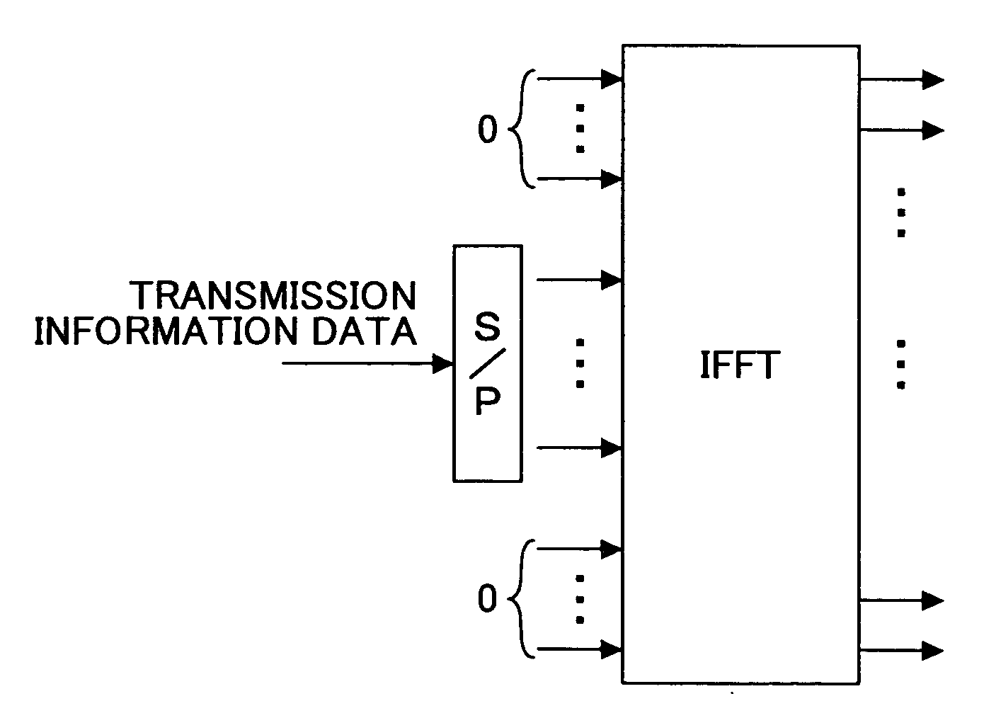
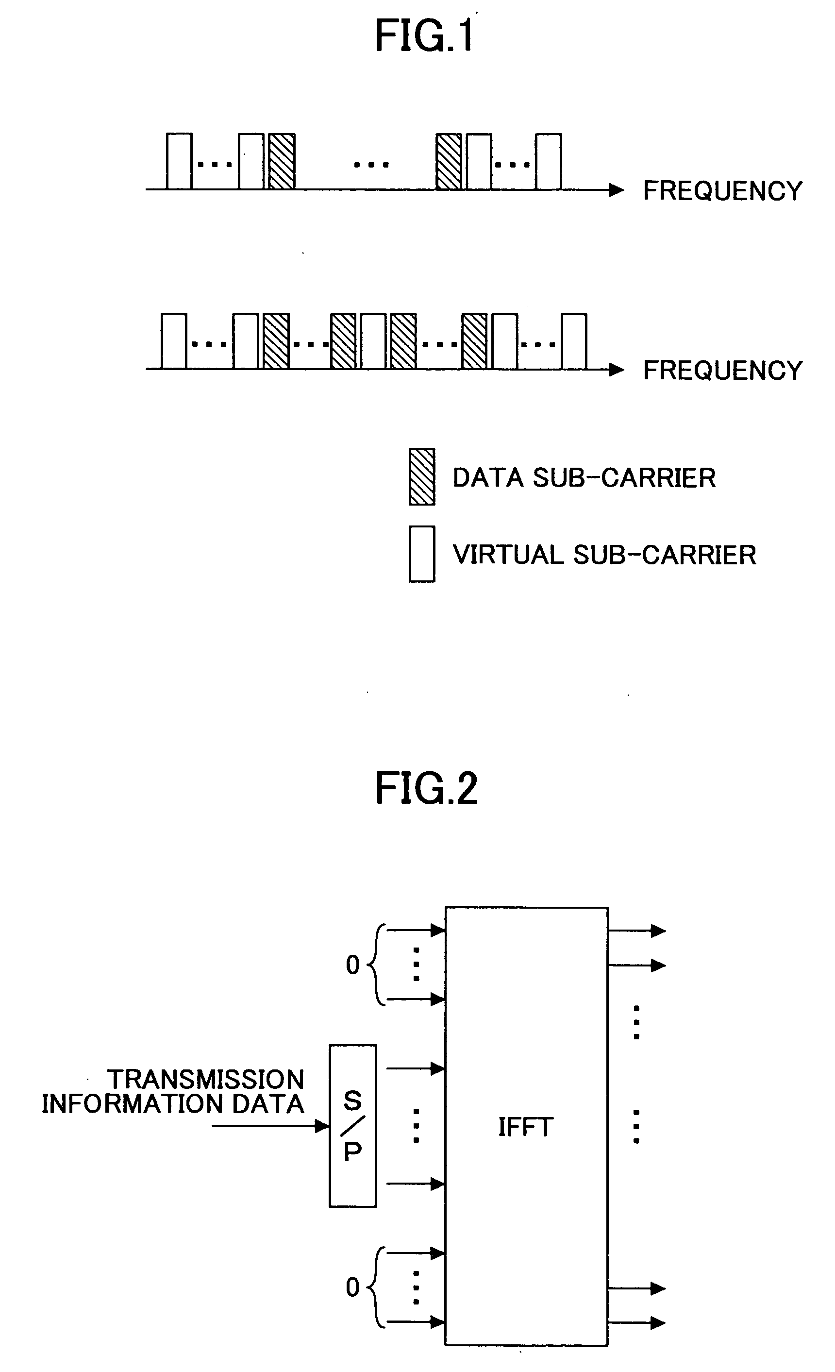
[0027] A communication system according to embodiments of the present invention may be implemented with the sub-carrier arrangements shown in FIG. 1, alternatively, implemented independently from these arrangements. At least some of the elements shown in the functional block diagrams presented below can be implemented, depending on specific applications, by software, by hardware, or by a combination of them.

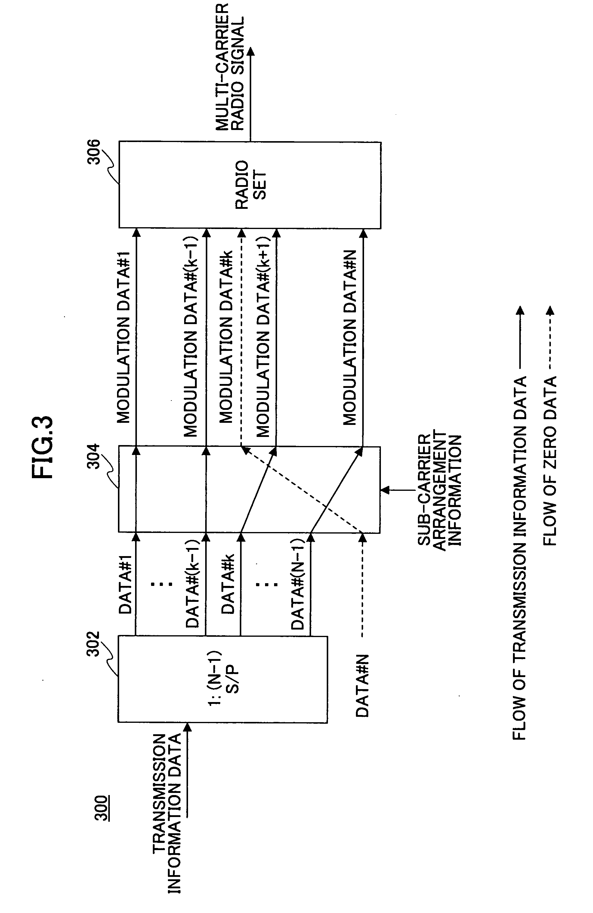
[0028]FIG. 3 is a block diagram illustrating principal functions of a transmission device according to an embodiment of the present invention.

[0029] A transmission device 300 has a series-parallel converter (S / P) 302, which sequentially extracts N−1 data points from a series signal including a series of transmission data, associates them with N−1 signal sequences, and outputs parallel signals. Here, N is an integer greater than or equal to 2. The series of transmission ...


PUM


Abstract

A multi-carrier radio transmission system able to improve frequency utilization efficiency, and a transmission device and a reception device used in the multi-carrier radio transmission system are disclosed. In the transmission device, at least one sub-carrier set to be the virtual sub-carrier is dynamically designated according to sub-carrier arrangement information. The reception device used in the above system includes an adaptive array antenna unit that is adaptively controlled so that signal components associated with the virtual sub-carriers in the received signals are reduced, and a determination unit that determines a pattern to be used in communications among plural sub-carrier arrangement patterns in which at least some of virtual sub-carrier arrangements are different. Because the virtual sub-carrier arrangement patterns can be used as identification information of radio signals, it is possible to improve utilization of frequency resources compared to the related art.

Description

CROSS-REFERENCE TO RELATED APPLICATION [0001] This application is a U.S. continuation application filed under 35 USC 111(a) claiming benefit under 35 USC 120 and 365(c) of PCT application JP2003 / 008277, filed Jun. 30, 2003. The application is hereby incorporated herein by reference.TECHNICAL FIELD [0002] The present invention relates to the technical field of mobile communications, particularly, to a multi-carrier radio transmission system, and a transmission device and a reception device used in such a system. BACKGROUND OF THE INVENTION [0003] In the present technical field, in addition to requirements of high speed and high quality communications, it is also necessary to meet the needs of increasing the number of users accommodated in the system, and it is important to efficiently utilize communication resources such as frequencies. [0004] A multi-carrier transmission method, which has attracted attention in recent years, uses plural sub-carriers to transmit data, thereby, for ex...

Claims


Application Information

Patent Timeline
IPC IPC(8): H04L27/26
CPCH04L27/2602H04B7/0848H04L5/0007H04L5/0046H04W16/10
Inventor HARA, SHINSUKE
Owner FUJITSU LTD
Why Eureka
Try Eureka