Omni-directional antenna in an hourglass-shaped vase housing

a vase-shaped, omni-directional technology, applied in the structure of resonant antennas, loop antennas, radiating elements, etc., can solve the problems of inability to adjust the length and direction of the dipole elements, the physical dimension of the vhf dipole is undetected, and the performance of such conventional indoor vhf/uhf antennas may change in response, so as to achieve good omni-directionality and good television signal reception. , good gain

Active Publication Date: 2010-11-18
VOXX INTERNATIONAL
View PDF5 Cites 27 Cited by
  • Summary
  • Abstract
  • Description
  • Claims
  • Application Information

AI Technical Summary

Benefits of technology

[0016]In accordance with one form of the present invention, an antenna, which is preferably for indoor use and constructed especially for receiving digitally formatted, broadcast television signals, exhibits good omnidirectionality and relatively high gain for good television signal reception to minimize or eliminate the need for the user to adjust the position of the antenna. In one form, the antenna is situated within an attractive, hourglass-shaped vase housing having generally conically-shaped upper and lower segments joined together to define a centered or off-centered relatively narrower diameter middle portion. The opposite top and bottom end portions of the housing defined respectively by the larger ends of the upper and lower segments thus are formed with a relatively larger diameter than that of the middle portion. The housing provides a form for supporting the antenna and otherwise plays no part in the functionality of the antenna, but rather provides an overall pleasing appearance for housing the antenna so that the user would be more inclined to display the housing in proximity to his television.

Problems solved by technology

One problem associated with the conventional indoor antenna systems is that the physical dimension of the VHF dipole is undesirably long for the ordinary setting in a living room and that the length as well as the direction of the dipole elements may need to be adjusted depending upon the receiving channels.
A second problem is that the performance of such conventional indoor VHF / UHF antennas changes in response to changes of the physical conditions around the antenna elements.
For example, it is difficult for a user to make proper adjustment of the antennas since a human body coming into contact with an antenna changes the electro-magnetic conditions associated with the antenna elements.
A third problem is that the conventional indoor antenna systems do not always provide a sufficient signal level for good reception.
A fourth problem associated with the “rabbit ears” antenna is that, while it is currently functional, it is far from being aesthetically attractive and its large size makes it difficult to conceal.
A fifth problem associated with the aforementioned antenna is that it is not well-suited for receiving digitally formatted, high definition, broadcast television signals.
Without a good omni-directional TV antenna, consumers will not be able to receive all of the digital ATSC signals with the broadcast format change that has come about.

Method used


Image

  • Omni-directional antenna in an hourglass-shaped vase housing
  • Omni-directional antenna in an hourglass-shaped vase housing
  • Omni-directional antenna in an hourglass-shaped vase housing

Examples


first embodiment

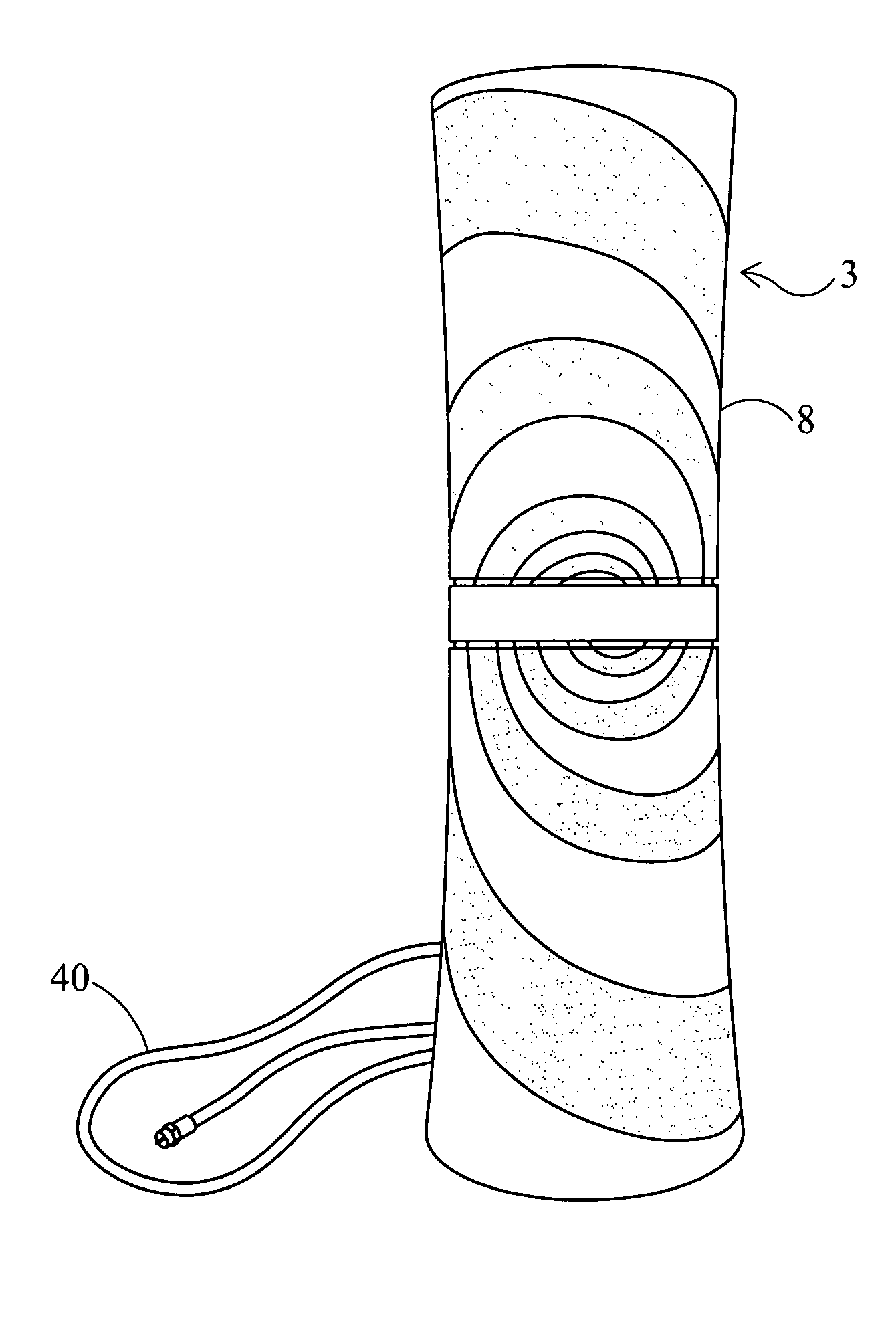
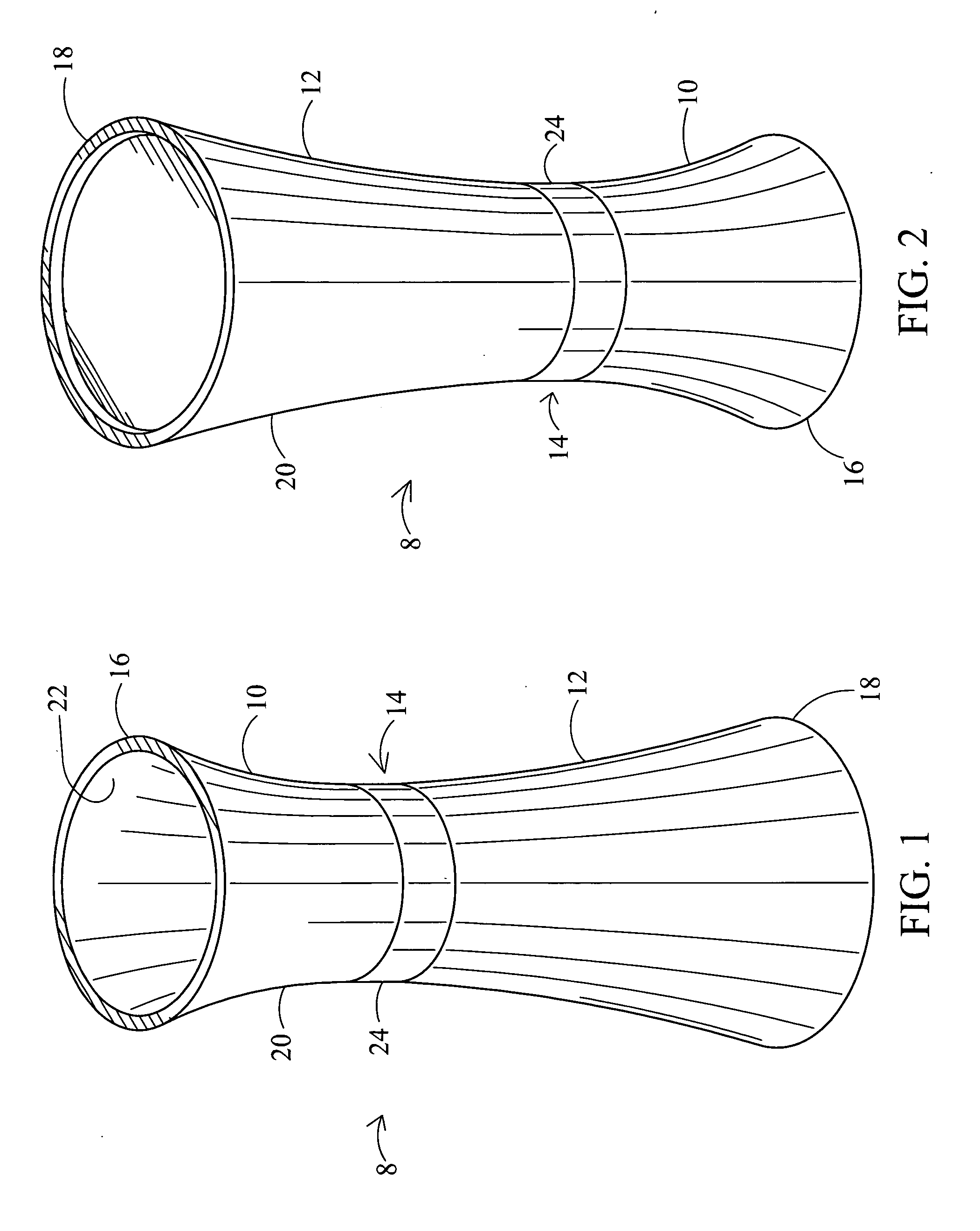
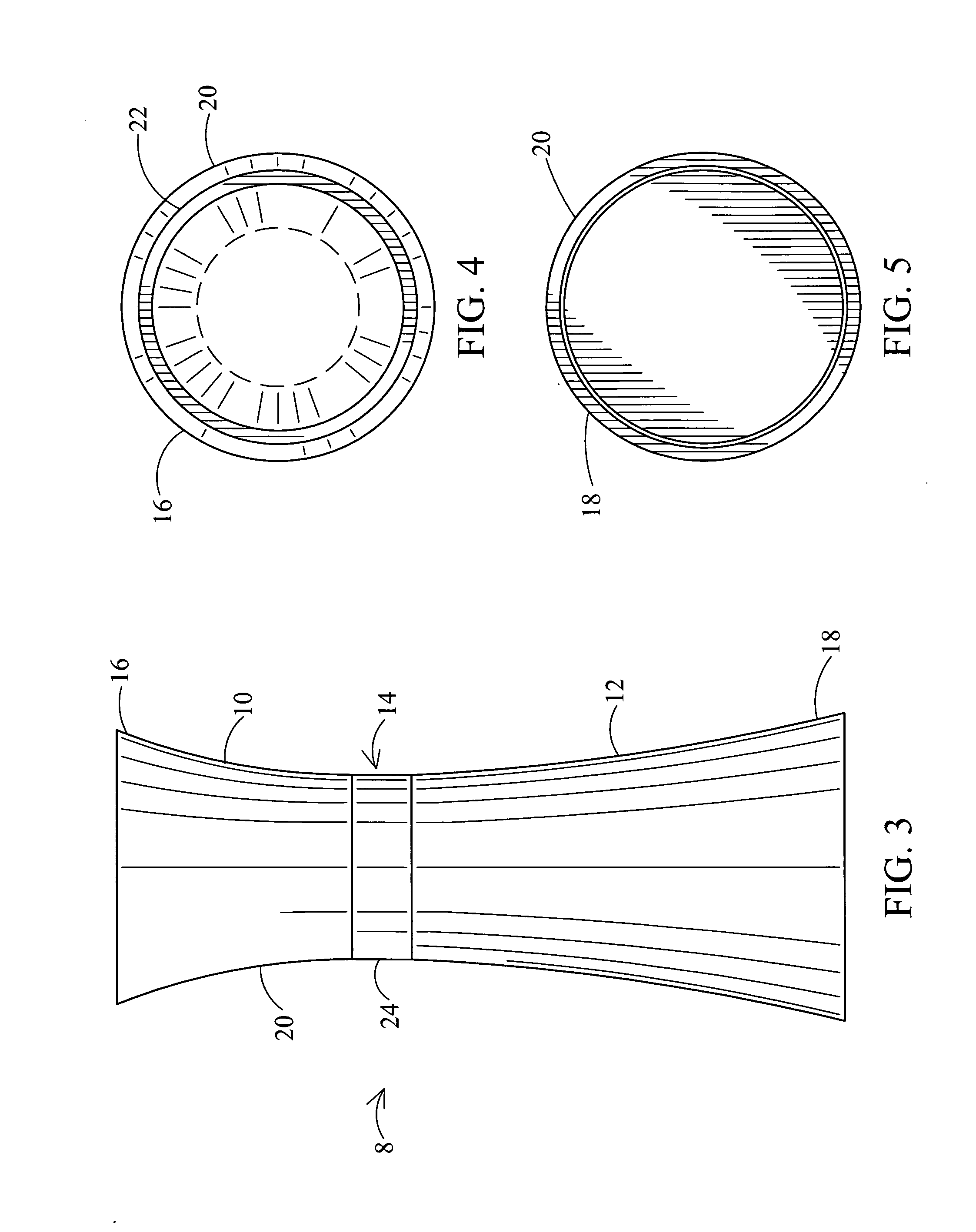
[0065]Three sets of tests were performed and measurements were taken for three different embodiments of the present invention. The first embodiment is a spiral antenna 3, such as shown in FIG. 6 of the drawings, situated within an hourglass-shaped vase housing 8 having a height of about 395 millimeters and symmetrical conically-shaped top and bottom segments which are joined at the center, each of the upper and lower conically-shaped segments 10, 12 having opposite end diameters of about 115 millimeters, the housing 8 having a relatively narrower middle portion 14 having a diameter of about 98 millimeters. The spiral antenna 3 is center fed.

[0066]The second embodiment of the present invention uses dual bowtie antennas 26, such as shown in FIG. 9 of the drawings, to define a cloverleaf antenna 4. The antenna 4 is housed in a smaller hourglass-shaped vase housing 8 from that of the first embodiment which was tested. The housing 8 includes non-symmetrical upper and lower conically-shap...

second embodiment

[0068]FIGS. 11, 15 and 19 are charts of antenna gain at vertical measured at selected frequencies respectively for each of the three aforementioned tested embodiments, the first being a relatively large housing 8 in which a spiral antenna 3 is situated, the second being a relatively smaller housing 8 having a cloverleaf antenna 4 situated therein and the third in the same sized housing 8 and having the same cloverleaf antenna 4 as the second embodiment but having the outer surface 20 of the housing painted.

[0069]FIGS. 12, 16 and 20 are graphs of antenna gain versus frequency respectively for each of the three tested embodiments of the present invention described previously.

[0070]FIGS. 13, 17 and 21 are graphs of VSWR (voltage standing wave ratio) plotted against frequency respectively for each of the three tested embodiments of the present invention mentioned previously.

[0071]FIGS. 14, 18 and 22 are radiation or antenna patterns at vertical measured at selected frequencies respectiv...


PUM


Abstract

An antenna structure for receiving digital television broadcast signals includes a vase antenna housing having a generally hourglass shape with conically-shaped upper and lower segments joined together to define a narrower diameter middle portion. The antenna structure further includes a signal receiving antenna etched on the inner surface of the vase antenna housing. The signal receiving antenna conforms to the shape of the vase antenna housing and thereby exhibits an arcuate, partial hourglass shape. The signal receiving antenna may be a cloverleaf antenna or a spiral antenna.

Description

CROSS-REFERENCE TO RELATED APPLICATION[0001]This application is related to U.S. Provisional Application Ser. No. 61 / 204,448, filed on Jan. 7, 2009, and entitled “Omni-Directional Antenna In An Hourglass-Shaped Vase Housing”, the disclosure of which is incorporated herein by reference. This application claims the benefit of priority under 35 U.S.C. 119 and / or 35 U.S.C. 120 to the aforementioned related provisional application.BACKGROUND OF THE INVENTION[0002]1. Field of the Invention[0003]The present invention generally relates to antennas for receiving broadcast signals such as television signals, and more specifically relates to television antennas for receiving digitally formatted broadcast signals.[0004]2. Description of the Prior Art[0005]Conventional indoor TV antenna systems generally include two separate antennas for respective VHF and UHF reception. The antenna for receiving the VHF bands employs a pair of telescopic elements forming a dipole with each of the elements having...

Claims


Application Information

Patent Timeline
Patent Type & Authority Applications(United States)
IPC IPC(8): H01Q1/36H01Q9/16
CPCH01Q1/22H01Q9/27H01Q7/00H01Q1/44
Inventor LENZI, LOUIS E.CASKEY, HENRY D.TINAPHONG, PRAPAN PAULBENEDETTI, DAVID A.HUNG, CHUNG HUAYIN, HONG
Owner VOXX INTERNATIONAL
Why Eureka
Try Eureka