License plate frame with antenna

a license plate and antenna technology, applied in the direction of road vehicle traffic control, traffic control system, instruments, etc., can solve the problems of undesirable display of such antennas on the outside of the vehicle, interference with the functioning of the antenna,

Inactive Publication Date: 2005-03-29
MOBILE MARK
View PDF3 Cites 25 Cited by
  • Summary
  • Abstract
  • Description
  • Claims
  • Application Information

AI Technical Summary

Problems solved by technology

However, when they are hidden inside of the vehicle, such as under the dashboard, seats, or the like, they are surrounded by metal components, which can

Method used


Image

  • License plate frame with antenna
  • License plate frame with antenna

Examples


Embodiment Construction

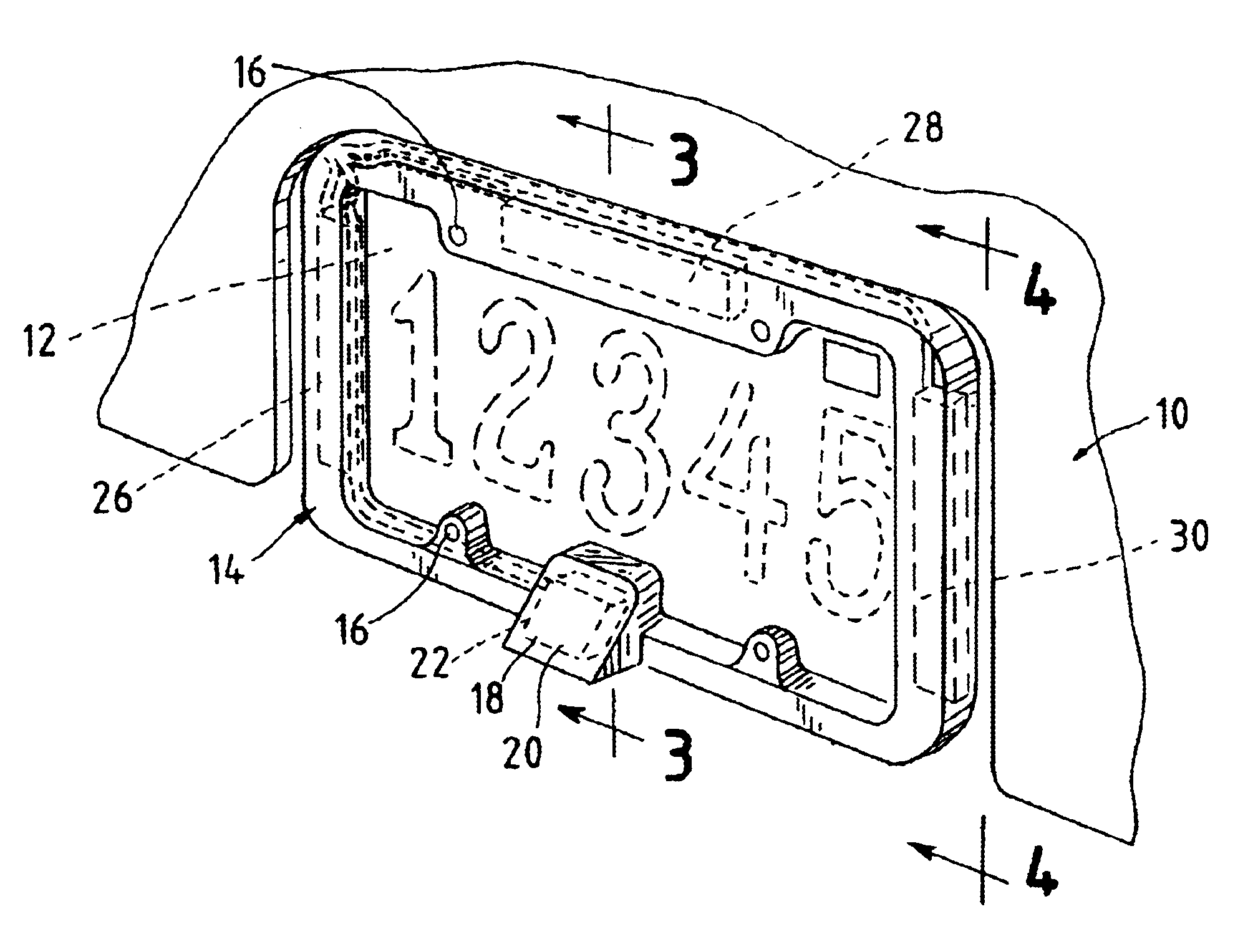
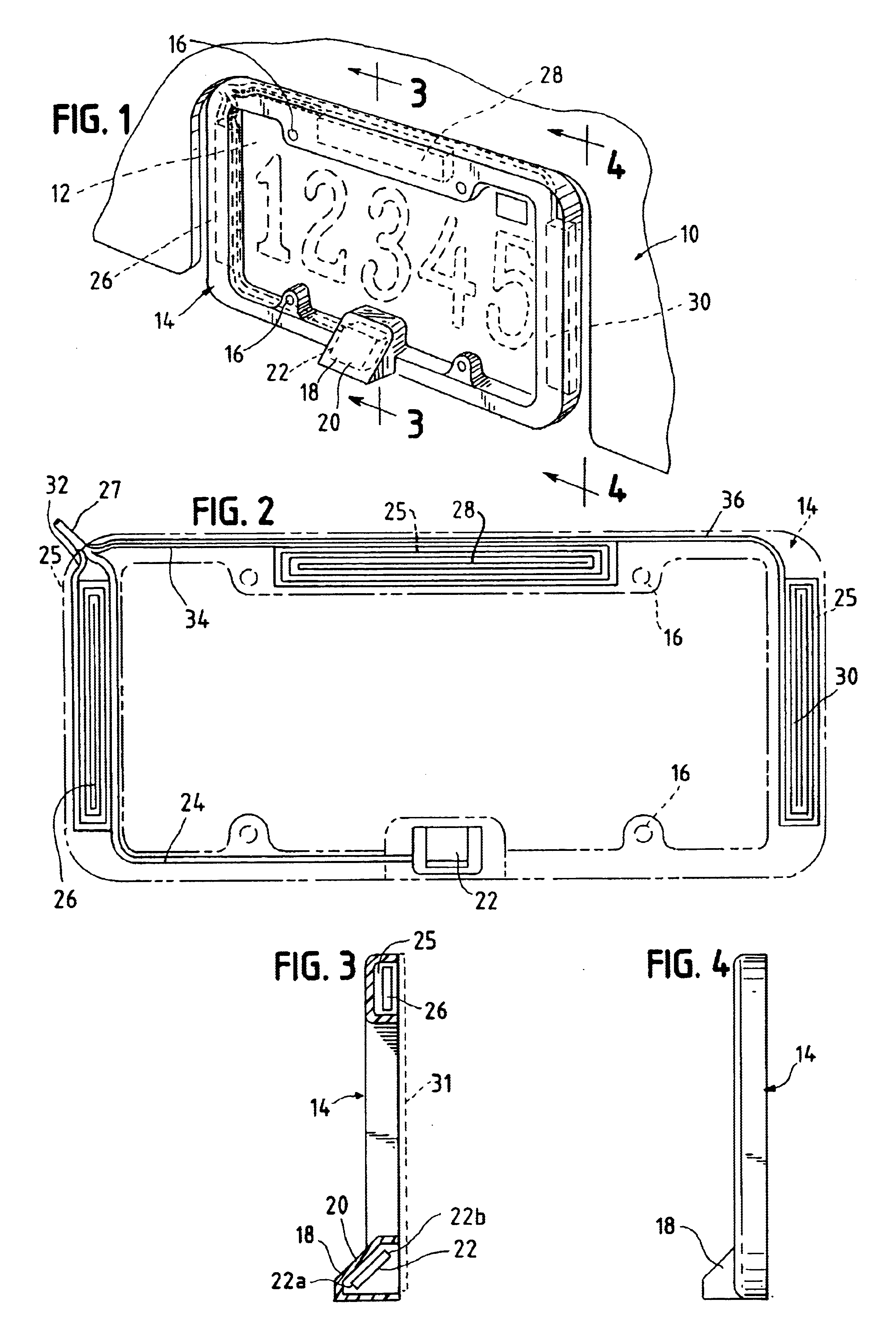
In accordance with this invention, a license plate frame assembly may be used to carry a global positioning satellite antenna, and also, as desired, additional antennas for different, desired systems such as cellular phone systems and other PCS systems such as pagers, wireless computer systems, e-mail systems, and other 2.4 GHz systems.

A plurality of antennas may be covertly mounted on a license plate frame, to provide multiple communication functions to the vehicle, where the antennas are outside of the vehicle for improved reception, but remain not readily noticeable (i.e. covert). Such antennas may, of course, be used for either or both transmitting and receiving signals.

In accordance with this invention, a license plate frame assembly comprises a license plate frame, having a seat member attached to the license plate frame. A first antenna is carried at the seat member in a position facing at an angle to the vertical, preferably with the antenna bottom positioned outwardly beyon...


PUM


Abstract

A license plate frame assembly comprises a license plate frame, a seat member attached to the license plate frame, and a first antenna carried at the seat member in a position facing at an angle from the vertical. Also, multiple antennas may be carried by the license plate frame.

Description

BACKGROUND OF THE INVENTIONWith the advent of the global positioning satellite system, automobiles commonly are capable of utilizing this system to determine location on a moment-by-moment basis. This, of course, requires an antenna that is carried by the vehicle.Similarly, cellular phone and other person communication (PCS) systems are also very popular as vehicle-mounted options, and they require antennas as well. Antennas for the various frequencies of such functions must be installed in the vehicle in which they are to be used, the term “vehicle” including, typically, ground vehicles, but also, as appropriate, including watercraft, aircraft, and the like.It is, of course, desirable that the antennas should be inconspicuous. However, when they are hidden inside of the vehicle, such as under the dashboard, seats, or the like, they are surrounded by metal components, which can interfere with the functioning of the antennas. However, the display of such antennas in a non-covert mann...

Claims


Application Information

Patent Timeline
IPC IPC(8): H01Q1/32H01Q1/44
CPCH01Q1/44H01Q1/325
Inventor POSLUSZNY, JERRY C.
Owner MOBILE MARK
Why Eureka
Try Eureka