Device and method for guiding electromagnetic waves

a technology of electromagnetic waves and devices, applied in waveguides, waveguides, particular array feeding systems, etc., can solve the problems of unbalanced currents of cables, inability to use mobile phones inside buildings, attenuation of even ten decibels, etc., to improve building thermal insulation, improve efficiency, and increase the reception area

Active Publication Date: 2017-09-21
STEALTHCASE
View PDF5 Cites 25 Cited by
  • Summary
  • Abstract
  • Description
  • Claims
  • Application Information

AI Technical Summary

Benefits of technology

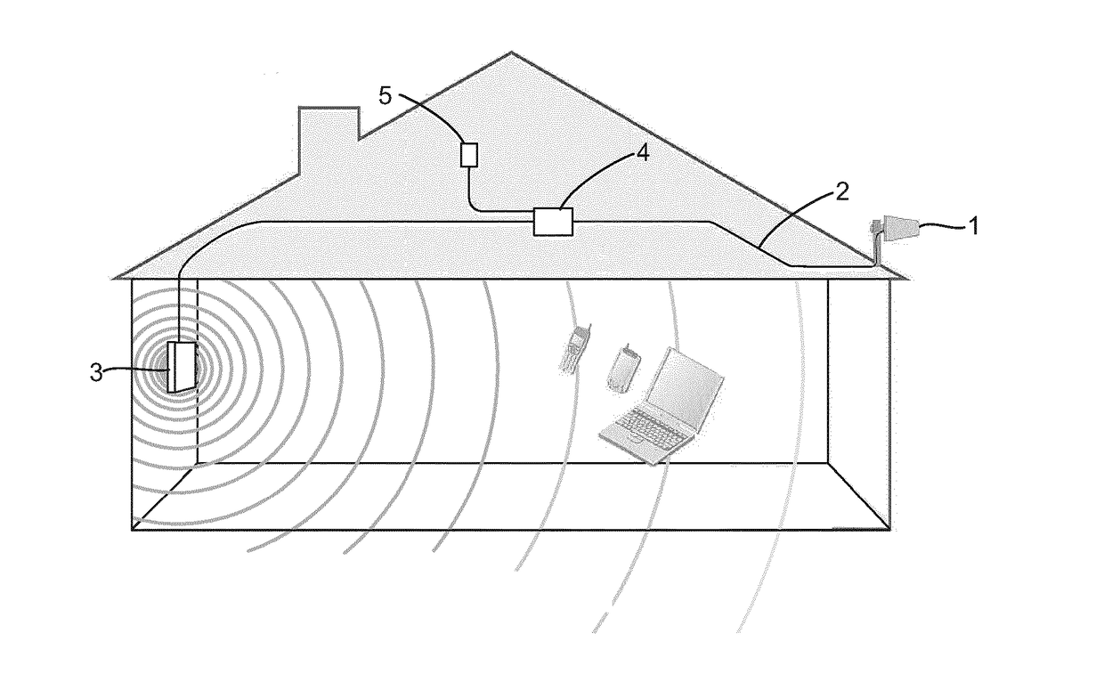
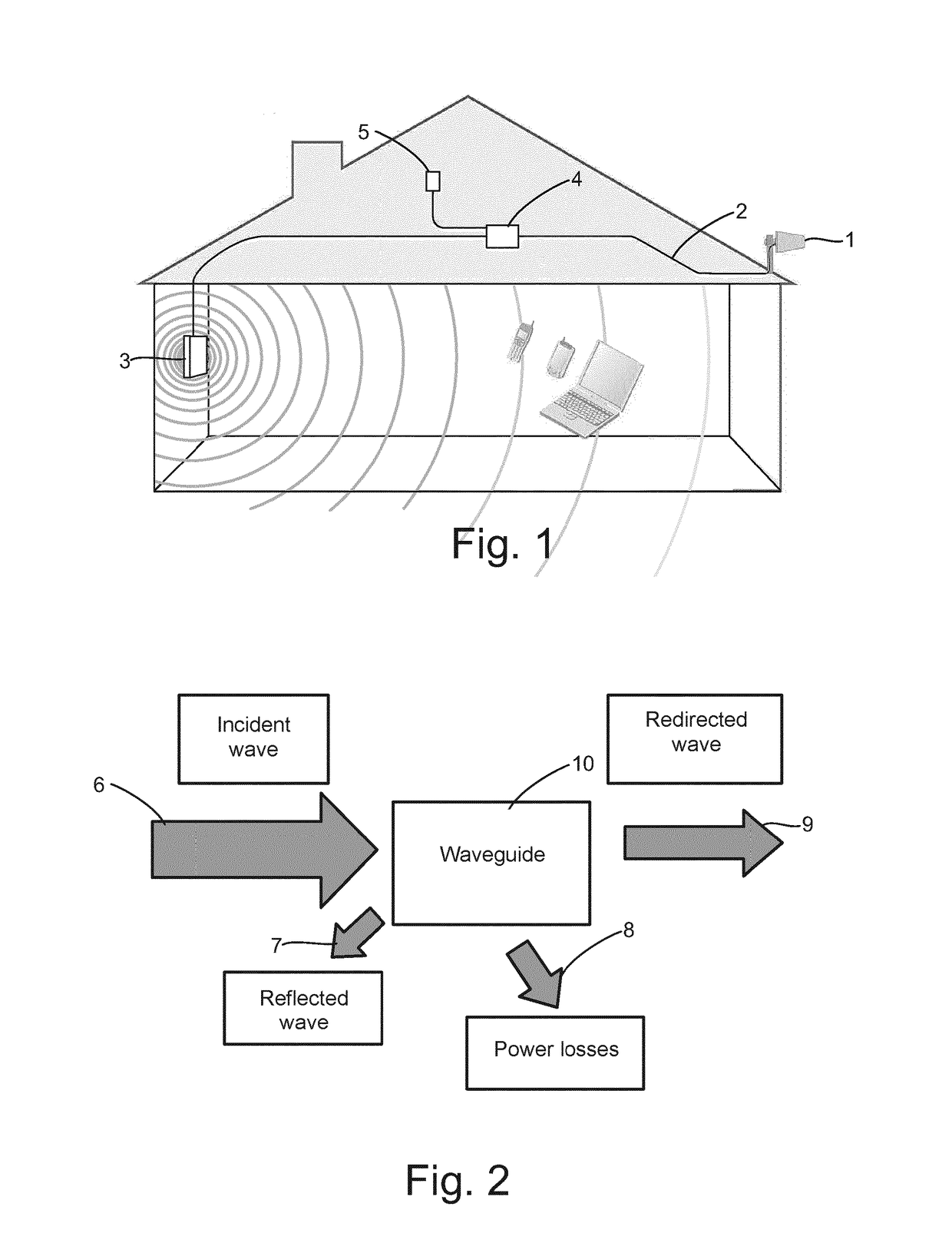
[0013]Smaller RF losses achieved by the waveguide, resulting from e.g. the fact that there is no need for a cable, give a better efficiency and thereby a larger reception area than a system implemented with a cable.
[0014]In an advantageous embodiment of the invention, the material for fabricating the structure is aluminium coated thermal insulation board that is used in buildings. For this reason, when installed in a wall, the waveguide according to this embodiment of the invention can also improve the thermal insulation of the building, so that it also has a non-electromagnetic functionality.

Problems solved by technology

Aims of the construction industry to build passive and zero energy buildings are leading to a situation in which efficient thermal insulation strongly attenuates the signals of mobile phones and other wireless systems, wherein it may be even impossible to use a mobile phone inside a building.
Conventionally, signals of wireless systems can enter buildings through windows, but the conductive coatings may cause an attenuation of even tens of decibels, depending on the frequency range.
A TEM waveform passes through the cable, and the currents of the cable are unbalanced.
Such an arrangement has, among other things, the drawback that the outdoor antenna may be difficult to position and may also be visually unaesthetic.
These disadvantages are pronounced if several antennas have to be mounted, for example, on the roof of the building to provide a sufficient signal strength.
A drawback among other things in this solution, too, is that the fitting between the antennas and the transfer line is not lossless.

Method used


Image

  • Device and method for guiding electromagnetic waves
  • Device and method for guiding electromagnetic waves
  • Device and method for guiding electromagnetic waves

Examples


Embodiment Construction

[0030]For the sake of clarity, some terms used in the description are now defined. A waveguide refers to a conductive structure that is capable of receiving electromagnetic radiation and re-radiating this received electromagnetic radiation. The waveguide is a tubular structure consisting of or coated with a conductive material, and intended for transmitting electromagnetic signals, particularly signals of high frequency (UHF, microwave range). The cross-sectional shape of the waveguide can be rectangular, square, triangular, polygonal, circular, or any other cross-sectional shape suitable for the purpose. A cavity resonator refers to a structure in which, upon propagation of electromagnetic signals, standing waves are formed at a frequency specific to the cavity resonator, that is, at the resonance frequency, or its multiples. To make this possible, the cavity resonator is provided with a surface that reflects electromagnetic radiation back, such as an end or ends of the cavity reso...


PUM


Abstract

A device for receiving and re-radiating electromagnetic signals. The device includes at least a waveguide with a first set of slot radiators for receiving electromagnetic signals, and a second set of slot radiators for transmitting electromagnetic signals generated on the basis of the received electromagnetic signals in the waveguide. The first set of slot radiators includes one or more slot radiators, and the second set of slot radiators includes one or more slot radiators. The device also relates to a method for receiving and re-radiating electromagnetic signals by a device including at least a waveguide, and the use of the device as a repeater of electromagnetic signals, for transferring electromagnetic signals through a structure, and/or as a building product.

Description

TECHNICAL FIELD[0001]The aspects of the disclosed embodiments relate to a device for guiding electromagnetic waves, comprising at least a waveguide. The invention also relates to a method for re-radiating received electromagnetic signals by a waveguide. Moreover, the aspects of the disclosed embodiments relate to the use of a structure that guides electromagnetic waves, for transmitting electromagnetic signals to a shadow area.BACKGROUND[0002]Aims of the construction industry to build passive and zero energy buildings are leading to a situation in which efficient thermal insulation strongly attenuates the signals of mobile phones and other wireless systems, wherein it may be even impossible to use a mobile phone inside a building. There are many reasons for the attenuation, but one reason that has been detected is the use of so called selective glass panes, that is, windows laminated with a conductive coating.[0003]Conventionally, signals of wireless systems can enter buildings thro...

Claims


Application Information

Patent Timeline
Patent Type & Authority Applications(United States)
IPC IPC(8): H04B7/145H01Q13/10H01Q1/12H01Q1/44H01Q13/22H01Q1/00
CPCH04B7/145H01Q13/22H01Q13/10H01Q1/1221H01Q1/44H01Q1/007H04B7/155H01Q21/005H01Q21/0056H01Q21/064E04B1/02E04C1/40H01Q1/1214H01P1/08H01Q13/28H01P3/121H01P7/06
Inventor LILJA, JUHA
Owner STEALTHCASE
Why Eureka
Try Eureka