Rotation detection apparatus

a detection apparatus and rotation detection technology, applied in the direction of electrical/magnetically converting the output of the sensor, galvano-magnetic devices, instruments, etc., can solve the problems of reducing sensitivity, the rotation detection apparatus cannot perform self-diagnosis to determine whether there is a failure, and the magnetic sensor cannot perform self-diagnosis to determin

Active Publication Date: 2009-10-08
DENSO CORP
View PDF6 Cites 66 Cited by
  • Summary
  • Abstract
  • Description
  • Claims
  • Application Information

AI Technical Summary

Benefits of technology

[0009]In view of the above and other difficulties, it is an objective of the present invention to provide a rotation detection apparatus that can perform self-diagnosis to determine whether there exists a failure such as a sensitivity reduction failure, an offset failure and the like.

Problems solved by technology

It is thereby possible to adjust a sensor output offset, which can result from a bias magnet magnetization variation and a relative positioning error between the MR element and the bias magnet etc.
However, when a detection target object is in a stationary state, the magnetic sensor cannot perform self-diagnosis thereof to determine whether there exist an abnormality, e.g., the decrease in sensitivity or the presence of the offset due to a failure or aging of the MR element and the bias magnet.
However, the rotation detection apparatus cannot perform self-diagnosis to determine whether there exists a failure, e.g., the decrease in sensitivity or the presence of the offset caused by failure or aging of the MR element and the bias magnet.
Further, since the rotation detection apparatus includes multiple magnetic sensors, manufacturing cost is high.

Method used


Image

  • Rotation detection apparatus
  • Rotation detection apparatus
  • Rotation detection apparatus

Examples


first embodiment

Modifications of First Embodiment

[0063]The first embodiment can be modified in various ways, examples of which are described below. In the first embodiment, after calculation of the potential difference ΔV at S40, the potential difference ΔV is compared to the predetermined threshold at S50. Further, when the potential difference ΔV is greater than or equal to the predetermined threshold, the middle voltage Vmid is calculated at S60, and the middle voltage Vmid is compared to the predetermined threshold at S70. Alternatively, the calculation of the middle voltage Vmid and the comparison of the middle voltage Vmid to the predetermined threshold may be performed prior to or parallel to the calculation of the potential difference ΔV and the comparison of the potential difference ΔV to the predetermined threshold.

[0064]In the first embodiment, both of the peak and bottom values of the sensor output are detected, and the self-diagnosis is performed to: check the presence of the sensitivi...

second embodiment

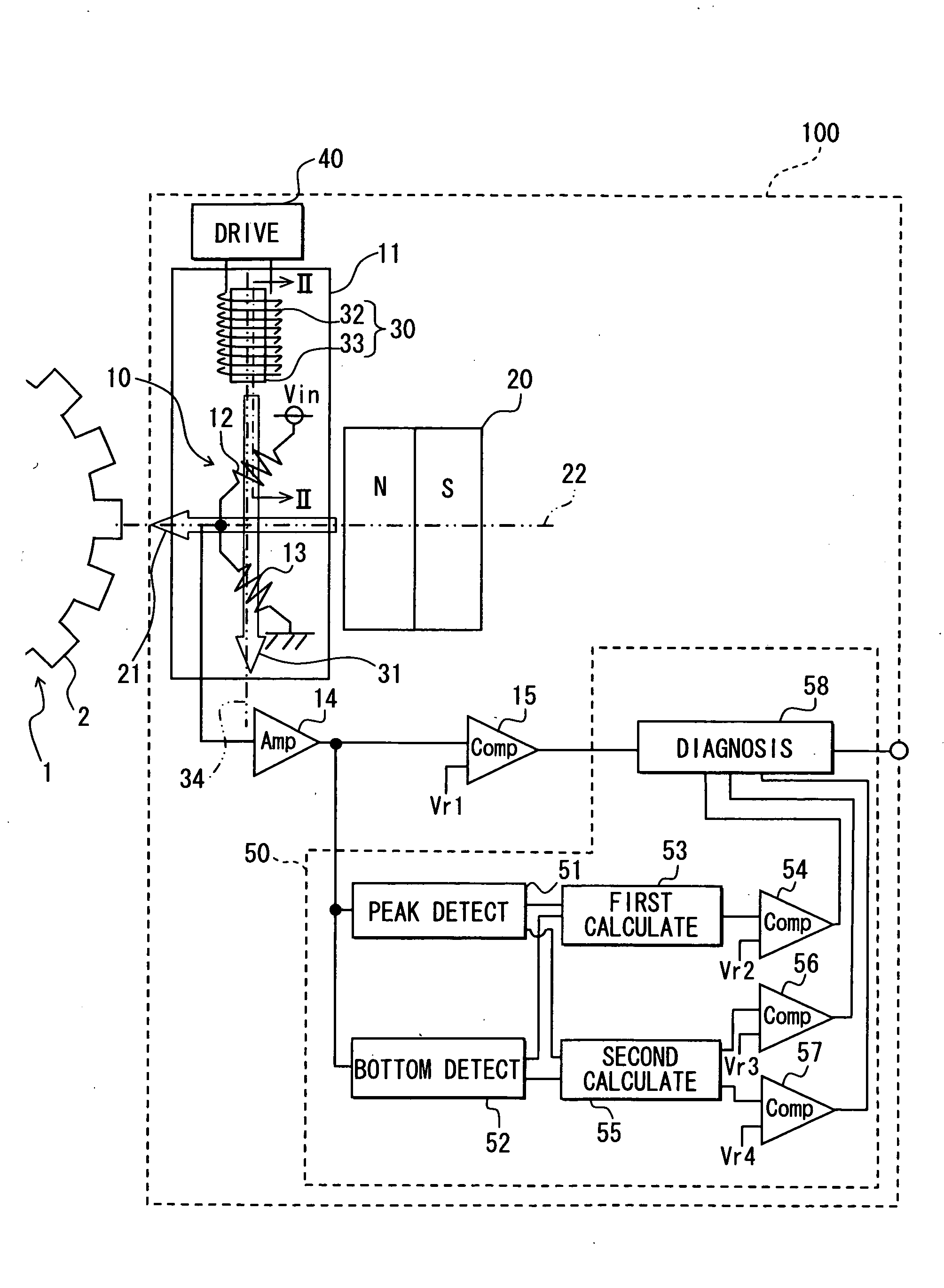
[0065]A second embodiment is described below with reference to FIGS. 9 to 12. FIG. 9 is a graph illustrating sensor output in a normal state and an offset failure state. FIG. 10 is a diagram illustrating a rotation detection apparatus according to the second embodiment. FIGS. 11A and 11B are diagrams each illustrating directions of superposition magnetic fields for cases where a forward electric current and a reverse electric current are applied. In FIG. 11A, the direction of the bias magnetic field 21 is generally parallel to the magnetic center line. In FIG. 11B, the direction of the bias magnetic field 21 is inclined clockwise at an angle θ1 with respect to the magnetic center line. FIG. 12 is a flow chart of a self-diagnosis method according to the second embodiment. Between the first and second embodiments, like parts refer to like reference numerals.

[0066]The rotation detection apparatus 100 of the present embodiment can perform self-diagnosis thereof to determine whether ther...


PUM


Abstract

A rotation detection apparatus for detecting a rotation state of a gear is disclosed. The rotation detection apparatus includes a magnetic sensor, a magnetic filed generation unit, and a self-diagnosis unit. The sensor includes: a bias magnet for generating a bias magnetic field extending toward the gear; and a magnetic-electric conversion element for sensing the bias magnetic field acting thereon. When the gear is in a stationary state, the magnetic filed generation unit generates a diagnosis use magnetic field extending toward the magnetic-electric conversion element. The self-diagnosis unit determines whether the magnetic sensor has a failure based on an output from the magnetic-electric conversion element that is subjected to the bias magnetic field and the self-diagnosis use magnetic field.

Description

CROSS REFERENCE TO RELATED APPLICATION[0001]The present application is based on Japanese Patent Application No. 2008-97537 filed on Apr. 3, 2008, the disclosure of which is incorporated herein by reference.BACKGROUND OF THE INVENTION[0002]1. Field of the Invention[0003]The present invention relates to a rotation detection apparatus including a magnetic-electric conversion element to detect a rotation state of a gear.[0004]2. Description of Related Art[0005]Japanese Patent No. 3988316 discloses a magnetic sensor that includes a bias magnet and a sensor chip having a magnetoresistive (MR) element. The bias magnet applies a bias magnetic field to the MR element. The magnetic sensor further includes an electric current conduction part disposed on a substrate on which the MR element is arranged. According to the above magnetic sensor, the electric current is applied to the electric current conduction part to adjust a direction of the bias magnetic field acting on the MR element. It is th...

Claims


Application Information

Patent Timeline
Patent Type & Authority Applications(United States)
IPC IPC(8): G01B7/30
CPCG01D5/24466G01D5/20G01D2205/80
Inventor UENOYAMA, HIROFUMI
Owner DENSO CORP
Why Eureka
Try Eureka