Camera Module

Inactive Publication Date: 2009-10-08
SHARP KK
View PDF7 Cites 26 Cited by
  • Summary
  • Abstract
  • Description
  • Claims
  • Application Information

AI Technical Summary

Benefits of technology

[0039]As is apparent from the above, the camera module of the present invention has the first protrusion protruding toward the opposed housing that is provided on the outer peripheral portion of the adjustment lens holder, and the second protrusion protruding toward the opposed adjustment lens holder that is provided on the portion surrounding the hole of the housing. Therefore, when the adjustment lens holder is finely adjusted in horizontal directions to the housing, the minimum value of the clearance between the adjustment lens holder and the housing can be made larger than zero and a space can be provided between the outer peripheral portion of the adjustment

Problems solved by technology

As a result, a problem arises that a shock is given to a camera module when equipment is dropped and thereby the camera module itself is damaged.
However, the “camera module” disclosed in patent document 1 has a problem that an adjustment for securing the performance of the optical system cannot be made after the lenses and the lens transfer mechanism have been assembled.
However, the “lens frame, lens barrel, and camera” disclosed in patent document 2 has a problem that even if the process of making eccentricity adjustments of lenses can be simplified, the elastic holding section

Method used


Image

  • Camera Module
  • Camera Module
  • Camera Module

Examples


Embodiment Construction

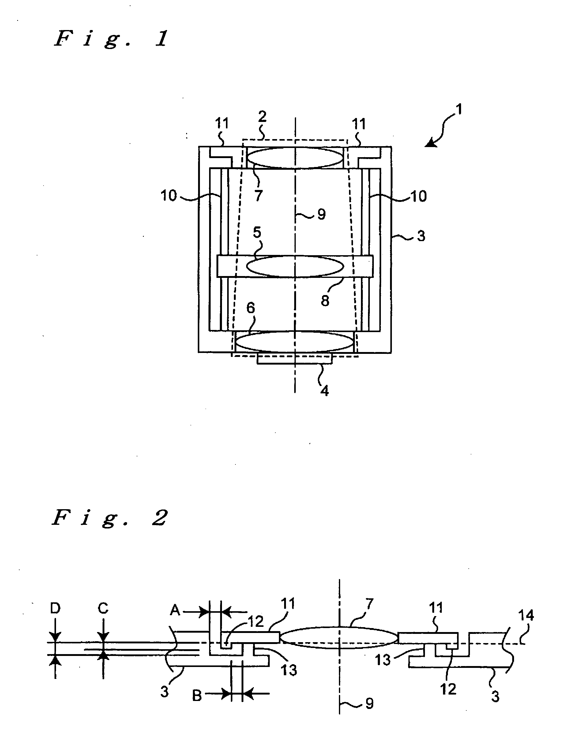
[0046]The present invention will be described in detail below with an embodiment shown in the drawings. FIG. 1 is a cross-sectional view showing the overall configuration of the camera module of this embodiment.

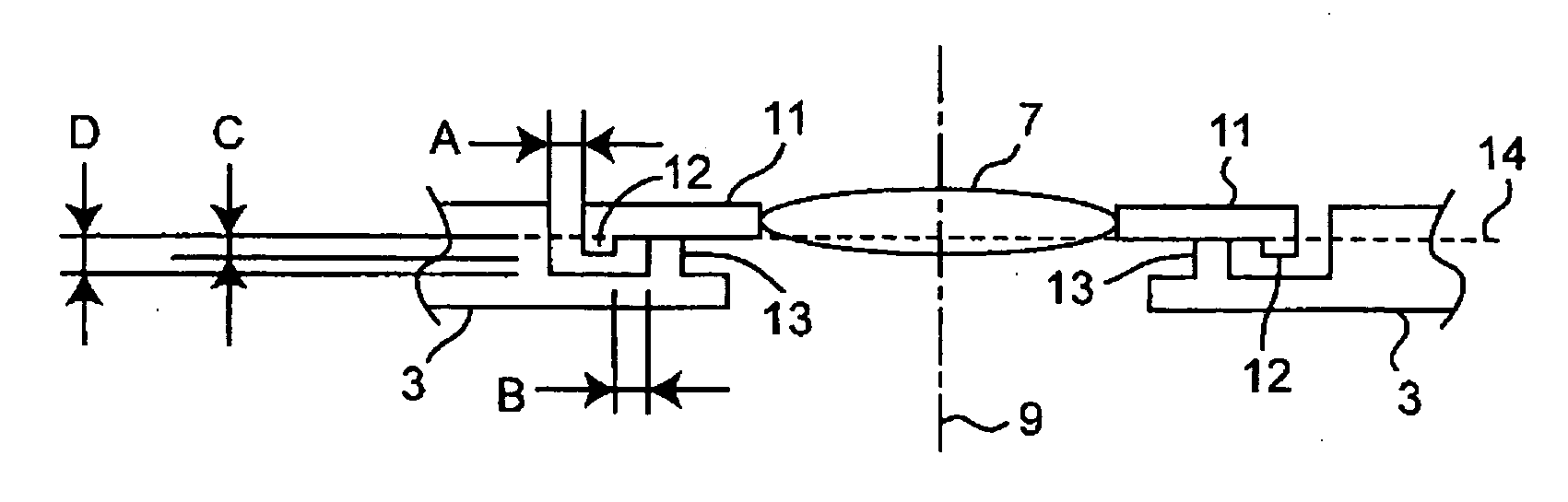
[0047]As shown in FIG. 1, the camera module 1 is roughly composed of an optical system 2 realizing optical high performance, a housing 3 holding the optical system 2, and an image pickup device 4 detecting light from the optical system 2. The optical system 2 has a scaling (i.e., magnification change) function and is composed of a movable lens 5 which enables wide angle shooting and telephoto shooting and is capable of focus adjustment, a fixed lens 6, and an adjustment lens 7. The adjustment lens 7 is for realizing eccentricity adjustment work performed to secure optical high performance after assembling the movable lens 5 and the fixed lens 6.

[0048]Each of the movable lens 5, the fixed lens 6, and the aliment lens 7 is drawn as one lens in FIG. 1, but may be composed of a p...


PUM


Abstract

On an outer peripheral portion of an adjusting lens holder (11), a ring-shaped first protrusion (12) is arranged to protrude to a housing (3). On an inner peripheral portion of the housing (3), a ring-shaped second protrusion (13) is arranged to protrude to the adjustment lens holder (11). The first protrusion (12) is arranged outside the second protrusion (13), an interval (B) between the both protrusions (12, 13) is smaller than a clearance (A) between the adjustment lens holder (11) and the housing (3), and the height of the first protrusion (12) is lower than that of the second protrusion (13). The minimum value of the clearance (A) is “A−B” and a space is provided between the first protrusion (12) adjacent to the clearance (A) and the housing (3). Thus, an adhesive is prevented from leaking out at the time of applying the adhesive in the clearance (A), and the space is filled with the adhesive. An optical system is prevented from breaking due to dropping impact by strongly fixing the adjusting lens holder (11) to the housing (3).

Description

BACKGROUND OF THE INVENTION[0001]1. Technical Field[0002]The present invention relates to a camera module including an optical system and an image pickup device.[0003]2. Background Art[0004]Camera modules incorporated into compact cameras, digital cameras, etc. are being sophisticated in functionality such as being configured to be capable of wide-angle shooting and telephoto shooting by coping with a large number of pixels of a few million pixels and having a scaling mechanism.[0005]In general, camera modules are provided with an optical system having a plurality of lenses and a substrate on which an image pickup device is mounted. In addition, in camera modules sophisticated in functionality, wide-angle shooting and telephoto shooting are enabled by increasing the number of pixels of an image pickup device and / or changing positions of a plurality of lens holders that are combined with a plurality of lenses.[0006]On the other hand, the need for reductions in size, thickness, and we...

Claims


Application Information

Patent Timeline
IPC IPC(8): G02B7/04G02B7/02
CPCG02B7/102G02B7/025
Inventor IWAI, YOSHIFUMI
Owner SHARP KK
Why Eureka
Try Eureka