Exhaust Assembly with Universal Multi-Position Water Trap

Active Publication Date: 2009-10-22
CUMMINS FILTRATION IP INC
View PDF16 Cites 23 Cited by
  • Summary
  • Abstract
  • Description
  • Claims
  • Application Information

AI Technical Summary

Benefits of technology

[0002]Exhaust assemblies typically include a housing having an inlet receiving exhaust, an outlet discharging the exhaust, an interior chamber through which the exhaust flows from upstream to downstream from the inlet along a downstream direction to the outlet, and an exhaust pipe extending from the outlet and directing the exhaust to atmosphere. A water trap may be provided in t

Problems solved by technology

This in turn requires that multiple parts and components be stocked in inventory, which is deemed not cost effective.
The u

Method used


Image

  • Exhaust Assembly with Universal Multi-Position Water Trap
  • Exhaust Assembly with Universal Multi-Position Water Trap
  • Exhaust Assembly with Universal Multi-Position Water Trap

Examples


Embodiment Construction

Prior Art

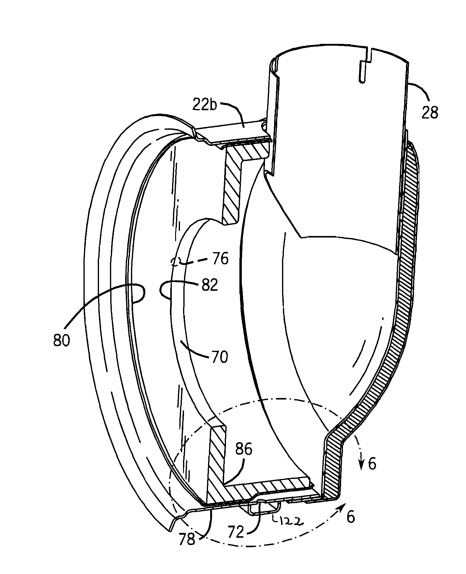
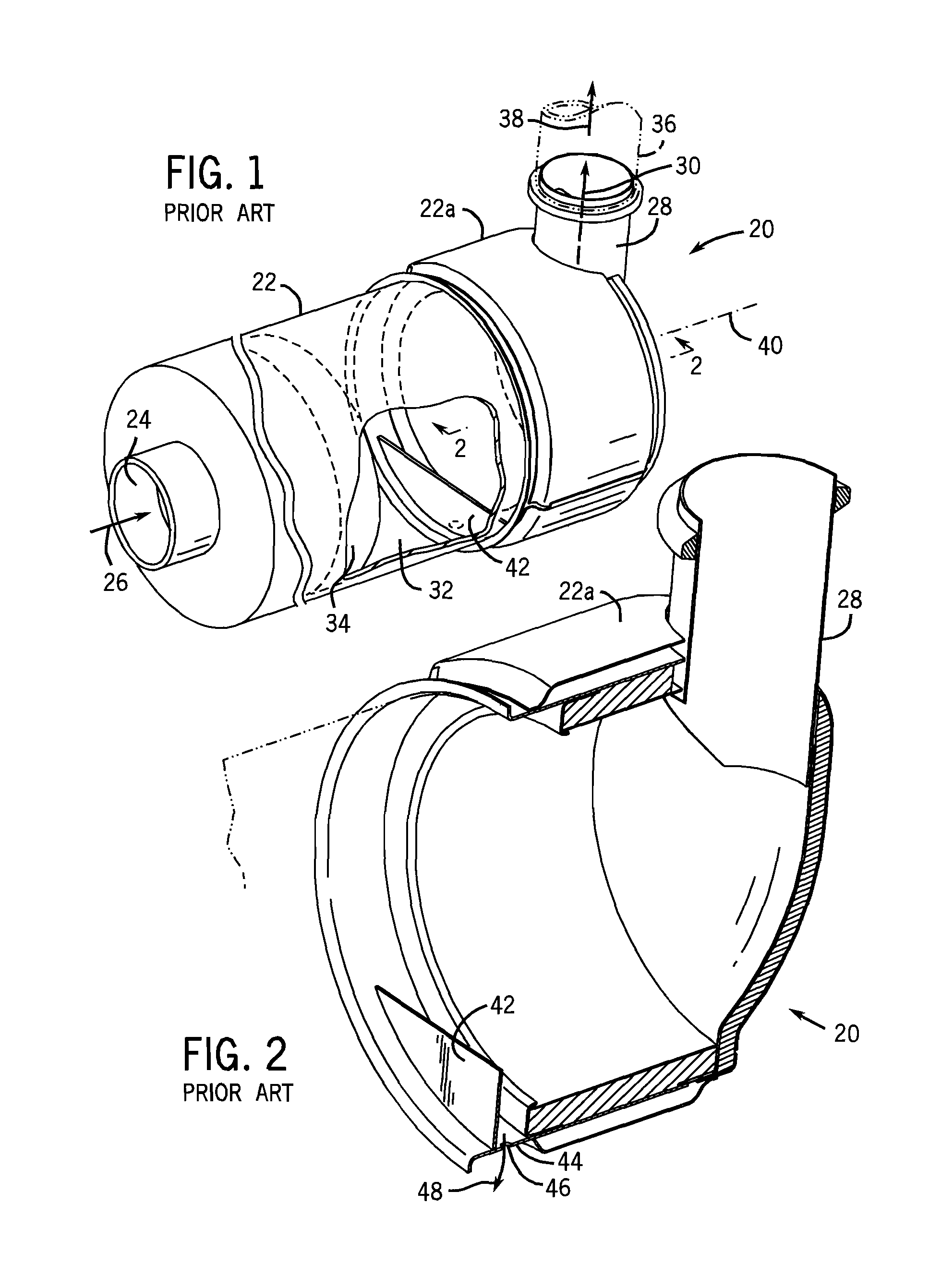
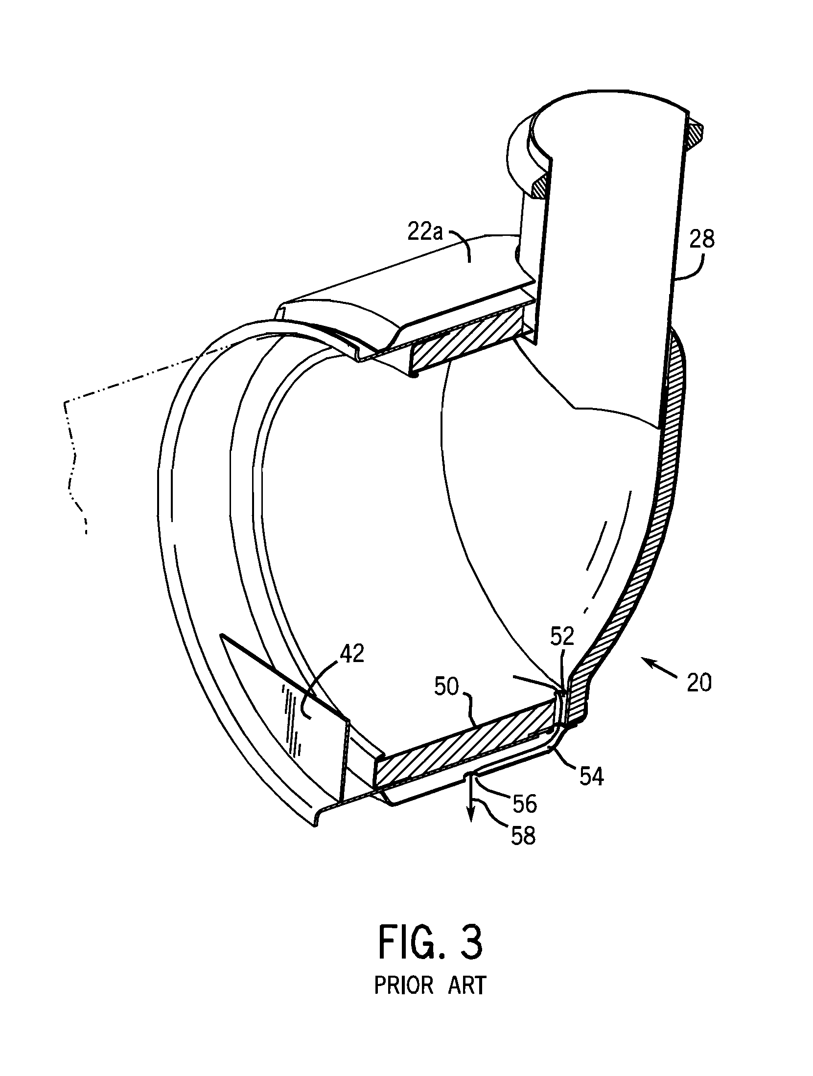
[0016]FIG. 1 shows an exhaust assembly 20 including a housing 22 having an inlet 24 receiving exhaust as shown at arrow 26, an outlet 28 discharging the exhaust as shown at arrow 30, an interior chamber 32 through which the exhaust flows from upstream to downstream (left to right in FIG. 1) from inlet 24 along a downstream direction (rightwardly in FIG. 1) to outlet 28. Interior chamber 32 may include an exhaust aftertreatment element, for example as shown in dashed line at 34, such as a catalytic element, filter, etc. An exhaust pipe 36 extends from outlet 28 and directs the exhaust to atmosphere as shown at arrow 38. Housing 22 extends axially along an axis 40 having at least a partial vector component extending horizontally. A water trap dam 42 is provided in the housing downstream of interior chamber 32 and upstream of outlet 28 and blocking water which may enter exhaust pipe 36 from flowing along an upstream direction (leftwardly in FIG. 1) into interior chamber 32. Th...


PUM


Abstract

An exhaust assembly includes a water trap blocking upstream water flow at a plurality of angular positions enabling universal application and flexibility of orientation.

Description

BACKGROUND AND SUMMARY[0001]The invention relates to exhaust assemblies having a water trap.[0002]Exhaust assemblies typically include a housing having an inlet receiving exhaust, an outlet discharging the exhaust, an interior chamber through which the exhaust flows from upstream to downstream from the inlet along a downstream direction to the outlet, and an exhaust pipe extending from the outlet and directing the exhaust to atmosphere. A water trap may be provided in the housing downstream of the interior chamber and upstream of the outlet and blocking water which may enter the exhaust pipe from flowing along an upstream direction into the interior chamber. This is desirable where the interior chamber has one or more components which may be damaged by water intrusion, for example exhaust aftertreatment elements such as catalysts, filters, etc.[0003]The present invention arose during continuing development efforts directed toward the above noted exhaust assemblies.BRIEF DESCRIPTION ...

Claims


Application Information

Patent Timeline
IPC IPC(8): F01N3/04F01N7/00
CPCF01N3/005Y02T10/20F01N2570/22F01N13/085Y02T10/12F01N3/02
Inventor CREMEENS, CHRIS M.GRIMM, DAVID M.WAKNIS, ASHISH S.LAMPS, MICHAEL J.
Owner CUMMINS FILTRATION IP INC
Why Eureka
Try Eureka