Fuel Cell Heating Device And Method For Operating Said Fuel Cell Heating Device

Inactive Publication Date: 2008-10-30
BAXI INNOTECH
View PDF7 Cites 22 Cited by
  • Summary
  • Abstract
  • Description
  • Claims
  • Application Information

AI Technical Summary

Problems solved by technology

Reformation normally ensues at temperatures from 500° C. to 800° C. The reformer catalyst cannot have any contact with oxygen because doing so would damage it or it would become so heavily oxid

Method used


Image

  • Fuel Cell Heating Device And Method For Operating Said Fuel Cell Heating Device
  • Fuel Cell Heating Device And Method For Operating Said Fuel Cell Heating Device

Examples


Embodiment Construction

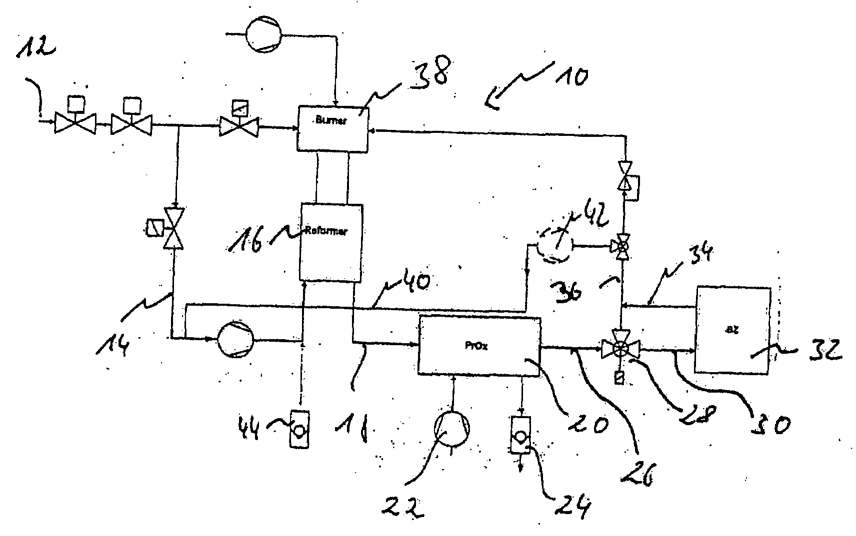
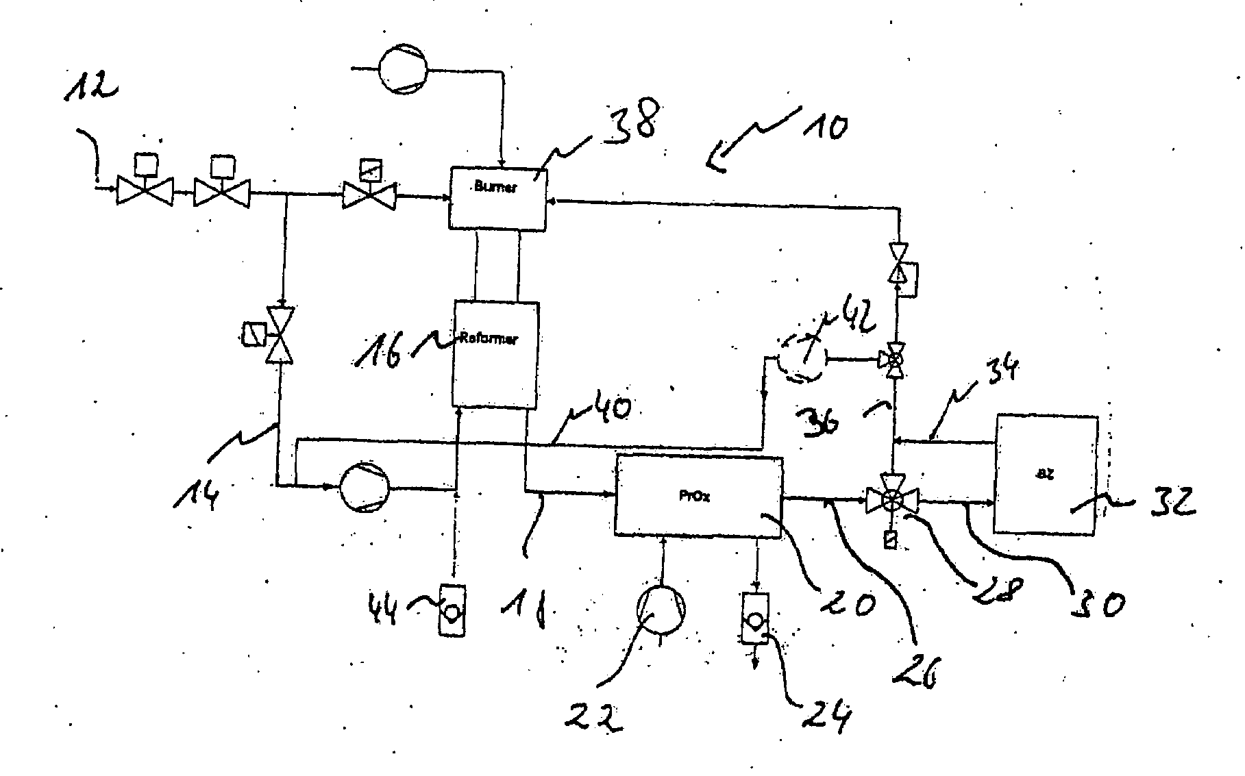
[0015]The fuel cell heating device 10 is fed process gas via a supply line. The process gas is fed to a reformer 16 via the line 14. The reformate from the reformer 16 is supplied to a PrOx stage 20 via a line 18. A supply of air 22 follows in PrOx stage 20 and the water which forms is discharged by a water trap 24. The gas which is formed in the PrOx stage 20 is conveyed by a line 26 through a three-way valve 28 and the three-way valve accordingly set for the fuel cell 32 through line 30.

[0016]The gas exiting the fuel cell 32 is fed via a line 34 to a line 36. The line 36 leads into a burner 38 which provides the process heat for the reformer 16. Branching off from the line 36 which forms the outlet line for the gas treatment unit is a circulation line 40 which connects the line 36 with the inlet line 16 for the reformer. The circulation line 40 is closed via a three-way valve 37 on the line 36. The three-way valve 37 allows a volume of gas to circulate, inclusive the fuel cell 32....


PUM


Abstract

A fuel cell heating device (10) comprising a gas treatment unit (16) having an inlet line (14) for gas and an outlet line (36) for hydrogenous reformate, wherein the inlet line and the outlet line are linked together by a circulation line in order to re-feed the reformate back to the gas treatment unit, wherein the gas treatment unit has a reformer and a downstream gas purification system comprising an inlet line for air and a water trap.

Description

CROSS-REFERENCE TO RELATED APPLICATIONS[0001]Not applicableSTATEMENT REGARDING FEDERALLY SPONSORED RESEARCH[0002]Not applicable[0003]The present invention relates to a fuel cell heating device as well as a method for operating said fuel cell heating device, in particular a method for starting up and shutting down a gas treatment unit in the fuel cell heating device.[0004]Fuel cells, such as polymer membrane fuel cells for example, are sufficiently known. Fuel cell heating devices for decentralized energy supply are fed natural gas through a gas supply connection, wherein the hydrogen is reformed from hydrogenous compounds of the natural gas. In a gas treatment unit containing a reformer, the hydrocarbons (CnHm) of the natural gas undergo endothermic reform in the presence of a catalyst by the addition of water vapor, wherein carbon dioxide (CO2) and hydrogen (H2) form. The reformate also contains residues of carbon monoxide (CO), which are selectively oxidized exothermically in a do...

Claims


Application Information

Patent Timeline
IPC IPC(8): H01M8/06H01M8/04
CPCH01M8/04022H01M8/04089H01M8/04223H01M8/0612H01M8/0662H01M2250/405Y02E60/50Y02B90/16Y02B90/10H01M8/04303H01M8/04302H01M8/04228H01M8/04225H01M8/04
Inventor SCHILLING, LUTZKLOSE, PHILIPPHOFFMANN, CHRISTIAN
Owner BAXI INNOTECH
Why Eureka
Try Eureka