Energy efficient gas separation for fuel cells

a fuel cell and gas separation technology, applied in the direction of hydrogen separation using solid contact, energy input, climate sustainability, etc., can solve the problems of degradation of cell voltage, serious limitations of prior art sofc systems, and serious limitations of high temperature operation of mcfc systems, so as to improve the overall efficiency of fuel cell systems, reduce the proportionate amount of carbon dioxide formed, and enhance oil recovery

Inactive Publication Date: 2002-10-03
AIR PROD & CHEM INC
View PDF80 Cites 178 Cited by
  • Summary
  • Abstract
  • Description
  • Claims
  • Application Information

AI Technical Summary

Benefits of technology

0034] The disclosed systems and processes can improve overall efficiency of fuel cell systems to reduce the proportionate amount of carbon dioxide formed, while enabling delivery as and when desired of that carbon dioxide in highly concentrated form for most convenient sequestration from the atmosphere, e.g. by underground disposal in depleted natural gas reservoirs or for enhanced oil recovery from petroleum reservoirs. In addition, exported power may be delivered only from the fuel cell stack, thus there is no export of power from a thermal bottoming cycle, or generators and associated gear boxes on the thermal bottoming turbines which are thus reduced to simple turbochargers. Instead, according to certain embodiments, the system utilizes high grade waste heat from the fuel cell stack to drive free rotor turbochargers as required for feed air compression, vacuum pumping of exhaust nitrogen-enriched air, and heavy reflux compression of carbon dioxide enriched anode tail gas; with the stack waste heat matched to these auxiliary loads so as to facilitate operation at high current density.
0035] The fuel cell stack can run at relatively high current density (e.g., about 200 to about 400 mA / cm.sup.2) to generate the required amount of waste heat for the auxiliary compression loads, since the disclosed PSA systems have dramatically raised open circuit voltages (e.g., about 0.75 to about 0.95 volts). The necessary size of the fuel cell stack size per kW can be reduced greatly at high current density. Equivalently, the same size fuel cell stack can achieve the full power output formerly achieved by the stack plus the thermal bottoming generator, which can be eliminated in certain disclosed embodiments.

Problems solved by technology

Prior art MCFC systems have serious limitations associated with their high temperature operation, and with their inherent need to supply carbon dioxide to the cathode while removing it from the anode.
Prior art SOFC systems face even more challenging temperature regimes, and are disadvantaged by the degradation of cell voltages at very high temperatures under conventional operating conditions.
Unfortunately, the reaction depletes the oxygen and carbon dioxide in the cathode channel and depletes hydrogen in the anode channel while rapidly increasing the backpressure of carbon dioxide in the anode channel.
This degrades the electrical efficiency of the system, while increasing the heat that must be converted at already lower efficiency by the thermal bottoming cycle.
Prior art MCFC systems do not provide any satisfactory solution for this problem which gravely compromises attainable overall efficiency.
The challenge is to devise a method for sustaining high hydrogen concentration over the anode and high oxygen concentration over the cathode, while efficiently transferring hot carbon dioxide from the anode to the cathode.
Despite repeated attempts to devise an effective carbon dioxide transfer technology that would be compatible with MCFC operating conditions, no such attempt has been adequately successful.
This approach has serious limitations.
Even more of the original fuel value is unavailable for relatively efficient electrochemical power generation, in view of additional combustion whose heat can only be absorbed usefully by the thermal bottoming cycle.
Also, the oxygen / nitrogen ratio of the cathode gas is even more dilute than ambient air, further reducing cell voltage and hence transferring more power generation load less efficiently onto the thermal bottoming plant.
This system is often cumbersome and expensive to implement due to the large size of the adsorbers and the complexity of the valving required.
The valves would not be capable of operation at MCFC working temperatures.
Further, the conventional PSA system makes inefficient use of applied energy because of irreversible gas expansion steps as adsorbers are cyclically pressurized and depressurized within the PSA process.
Conventional PSA systems are bulky and heavy because of their low cycle frequency and consequent large adsorbent inventory.
In addition, prior art PSA technology may not be capable of operation at such high temperature.

Method used


Image

  • Energy efficient gas separation for fuel cells
  • Energy efficient gas separation for fuel cells
  • Energy efficient gas separation for fuel cells

Examples


Embodiment Construction

FIGS. 1-5

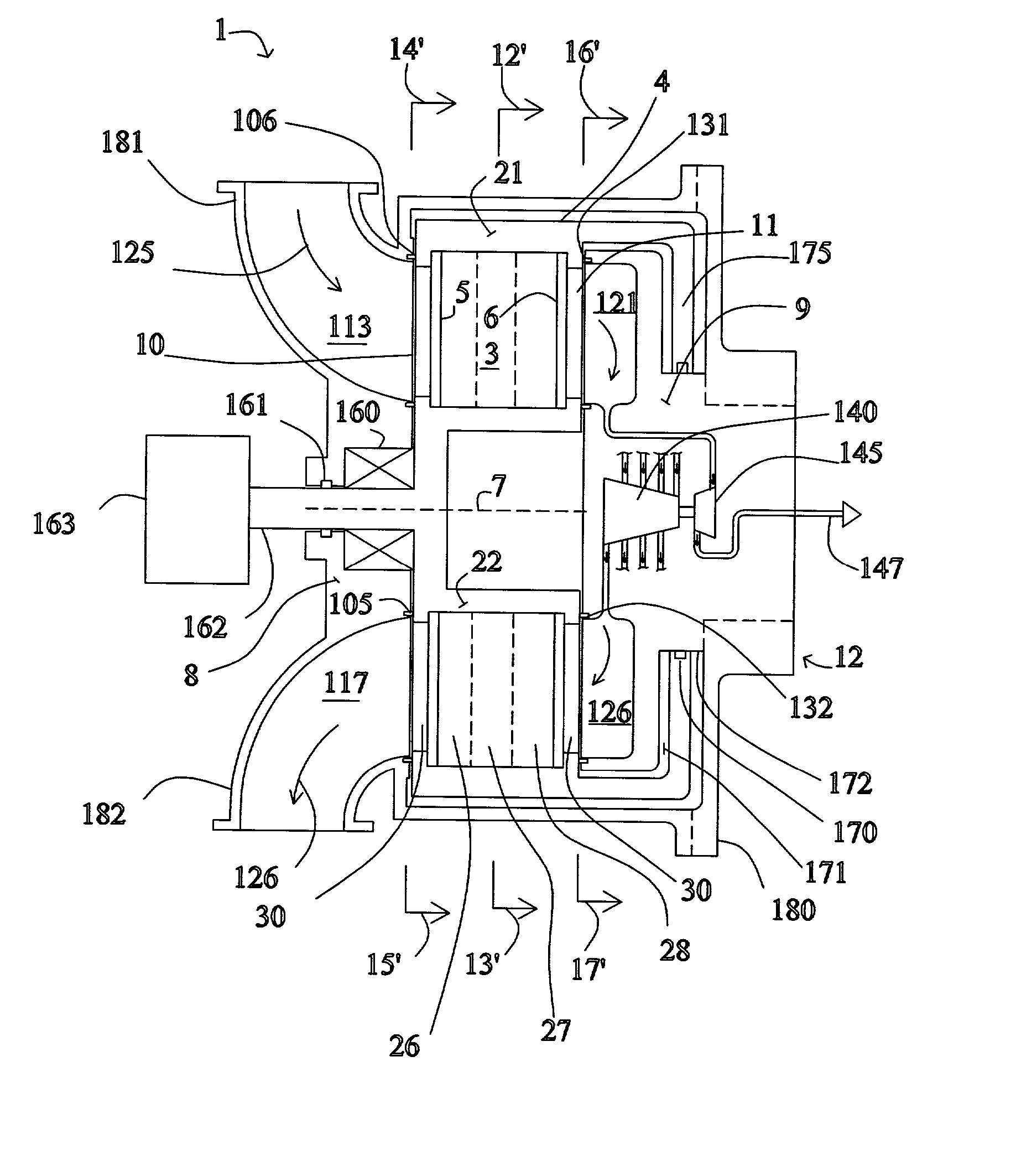
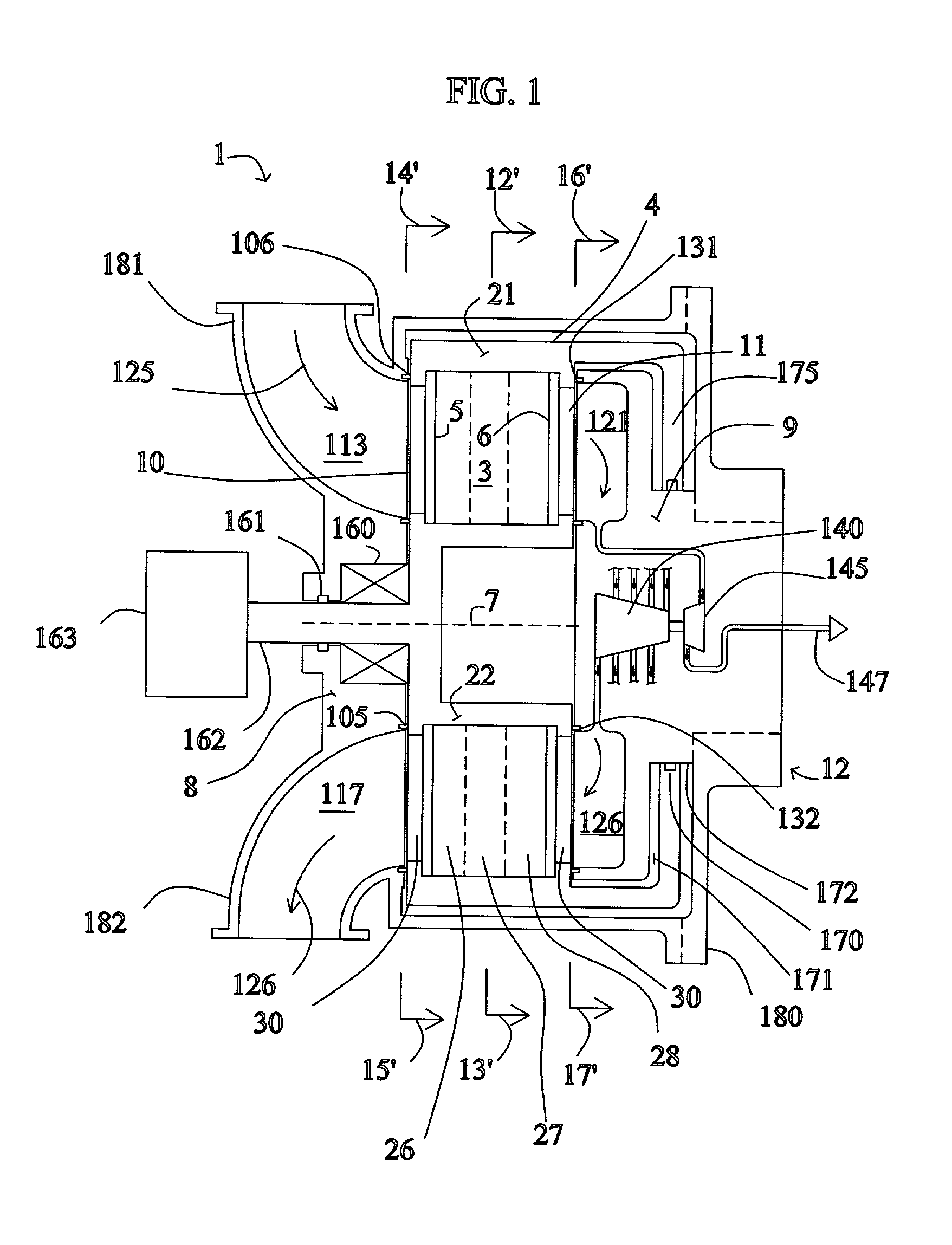
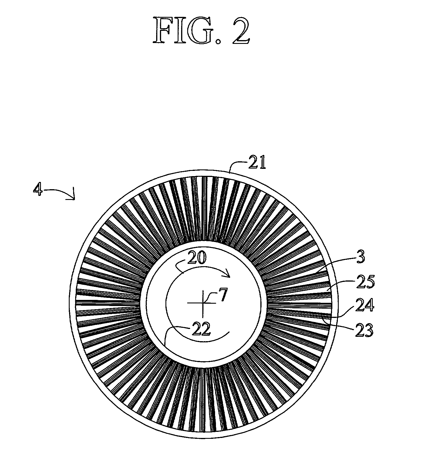
[0042] An oxygen-enrichment rotary PSA module is described below in connection with FIGS. 1-5B, but the same or similar rotary PSA module configuration could be used for hydrogen enrichment (i.e., separation) in the disclosed electrical current generating systems. As used herein, a "rotary PSA" includes, but is not limited to, either a PSA wherein an array of adsorbers rotates relative to a fixed valve face or stator or a PSA wherein the valve face or stator rotates relative to an array of adsorbers.

[0043] FIG. 1 shows a rotary PSA module 1, which includes a number "N" of adsorbers 3 in adsorber housing body 4. Each adsorber has a first end 5 and a second end 6, with a flow path therebetween contacting a nitrogen-selective adsorbent (for oxygen enrichment). The adsorbers are deployed in an axisymmetric array about axis 7 of the adsorber housing body. The housing body 4 is in relative rotary motion about axis 7 with first and second functional bodies 8 and 9, being engaged a...


PUM

PropertyMeasurementUnit
temperatureaaaaaaaaaa
operating temperatureaaaaaaaaaa

Abstract

An electrical current generating system is disclosed that includes a fuel cell operating at a temperature of at least about 250° C. (for example, a molten carbonate fuel cell or a solid oxide fuel cell), a hydrogen gas separation system or oxygen gas delivery system that includes a compressor or pump, and a drive system for the compressor or pump that includes means for recovering energy from at least one of the hydrogen gas separation system, oxygen gas delivery system, or heat of the fuel cell. The drive system could be a gas turbine system. The hydrogen gas separation system or the oxygen gas delivery system may include a pressure swing adsorption module.

Description

[0001] This application claims the benefit of Canadian Patent Application No. 2,325,072, filed Oct. 30, 2000, and U.S. Provisional Application No. 60 / 323,169, filed Sep. 17, 2001, the disclosures of which are incorporated herein by reference.[0002] The present disclosure relates to a fuel cell-based electrical generation system, which employs pressure swing adsorption for enhancing the energy efficiency of fuel cells, particularly high temperature fuel cells such as molten carbonate and solid oxide fuel cells.[0003] Fuel cells provide an environmentally friendly source of electrical current. One type of high temperature fuel cell used for generating electrical power, particularly envisaged for larger scale stationary power generation, is the molten carbonate fuel cell (MCFC). The MCFC includes an anode channel for receiving a flow of hydrogen gas (or a fuel gas which reacts in the anode channel to generate hydrogen by steam reforming and water gas shift reactions), a cathode channel...

Claims


Application Information

Patent Timeline
Patent Type & Authority Applications(United States)
IPC IPC(8): B01D53/06H01M8/04111C01B3/50C01B3/56C01B13/02H01M8/0668H01M8/14
CPCB01D53/047Y02E60/526B01D53/06B01D53/261B01D2251/306B01D2251/606B01D2253/104B01D2253/108B01D2253/25B01D2256/12B01D2256/16B01D2256/22B01D2257/504B01D2257/80B01D2258/0208B01D2259/40001B01D2259/40005B01D2259/4145C01B3/56C01B13/0259C01B2203/043C01B2203/0475C01B2203/0495C01B2203/066C01B2203/86C01B2210/0046C01B2210/0051C01B2210/0062H01M8/04007H01M8/04022H01M8/04089H01M8/04119H01M8/0612H01M8/0662H01M2008/1293H01M2008/147Y02C10/08Y02E60/50Y02E60/525B01D53/0476Y02C20/40Y02P20/10Y02P20/129Y02P20/151Y02P20/50Y02P30/00
Inventor KEEFER, BOWIE G.CONNOR, DENIS J.HUNTER, CARL F.
Owner AIR PROD & CHEM INC
Why Eureka
Try Eureka