Process and system for converting carbonaceous feedstocks into energy without greenhouse gas emissions

a technology of carbonaceous feedstocks and conversion systems, applied in the field of gas, can solve the problems of requiring an air separation plant, unable to eliminate the emissions of carbon dioxide and other greenhouse gases, and a problem source of carbon dioxide and other greenhouse gases, and achieves the effects of high hydrogen content, substantial carbon dioxide, and high efficiency

Active Publication Date: 2007-05-03
RAVEN SR INC
View PDF4 Cites 178 Cited by
  • Summary
  • Abstract
  • Description
  • Claims
  • Application Information

AI Technical Summary

Benefits of technology

[0013] The carbon dioxide in the fuel cell is easily kept separate from the air side and any nitrogen. The carbon dioxide can be recycled back to the gasifier in nearly pure form. Likewise steam in pure form can be recycled as well in different amounts under gasifier control system requirements to maintain the ideal hydrogen to carbon monoxide ratio in the range of about 0.7 to about 1.75. This helps maintain high hydrogen content in the gasifier so that a portion of the gasifier-produced syngas can be used downstream in a chemical reactor such as a Fischer Tropsch reaction system for the production of a variety of useful chemicals ranging from methanol to paraffin waxes. These in turn are used to make useful chemicals such as naphtha, gas oil, and kerosine, or agricultural chemicals or carbide abrasives. The latter are not ever burned in their lifecycle, and they sequester the carbon forever. Thus, the carbon monoxide is used to produce useful chemicals instead of discarding the valuable carbon source in the carbon dioxide. The carbon balance of the plant is maintained such that the mass of carbon input in the waste feed is equal to the carbon mass leaving the plant as valuable hydrocarbon products; not carbon dioxide.

Problems solved by technology

The burning of fossil fuels in boilers to raise high temperature, high-pressure steam that can be used to power turbo-electric generators produces a problem source of carbon dioxide and other greenhouse gases, e.g. methane, ozone and fluorocarbons.
However, to date none of these clean coal demonstrations eliminate the emissions of carbon dioxide and other greenhouse gases.
Efforts to use pure oxygen in power plants and gasification systems to avoid the diluting effects of nitrogen and to achieve higher efficiency suffers from the unacceptable cost of requiring an air separation plant and the problems of excessive temperatures in oxygen-fed combustion turbo-generators.
The problem with the conventional approach with high temperature fuel cells, which commingles the exhaust from the anode and cathode is that nitrogen and CO2 are mixed, making it very difficult and uneconomic to use the CO2 for sequestration applications (see U.S. Dept. of Energy, National Energy Technology Laboratory, “Solid State Energy Conversion Alliance (SECA) Program,” Pittsburgh, Pa., Aug. 29, 2006 and “7th Annual SECA Workshop and Peer Review,” Philadelphia, Pa., Sep. 12-14, 2006).
Today there is worldwide concern that the atmospheric buildup of carbon dioxide and other greenhouse gases will start to have serious environmental consequences for the earth's tropospheric temperature, global rainfall distribution, water balance, severe weather storms, and similar consequences.
This has, indeed, been a very large challenge with poor successes as summarized by the review papers; see Michele Aresta, and Eugenio Quaranta, “Carbon Dioxide: A Substitute for Phosgene,” Chem. Tech. pp.
Trying to scrub the CO2 from stack gases and trying to chemically react the recovered CO2 clearly is not the right path of research because of the technical difficulty and the process expense of reacting carbon dioxide.

Method used


Image

  • Process and system for converting carbonaceous feedstocks into energy without greenhouse gas emissions
  • Process and system for converting carbonaceous feedstocks into energy without greenhouse gas emissions
  • Process and system for converting carbonaceous feedstocks into energy without greenhouse gas emissions

Examples


example

[0038] The first step in the reduction to practice of the subject invention was to conduct experimental, small-scale pilot tests to reveal the identity and nature of the syngas produced. Accordingly, just completed was a gas test using the Bear Creek Pilot plant where solid waste was steam / CO2 reformed to make syngas. The syngas composition is shown in Table 1 below.

TABLE 1Results from Pilot Plant Gas Test By Steam / CO2Reforming Of Solid WasteH2Hydrogen62.71vol %COCarbon Monoxide18.57CO2Carbon Dioxide10.67CH4Methane7.58C2H6Ethane0.48C3 TO C6Propane through hexaneC6H6BenzeneppmCOSCarbonyl Sulfide4ppmCS2Carbon Disulfide0.05ppmH2SHydrogen SulfideppmC10H8Naphthalene2.6ppbC10H7CH32-Methylnaphthalene˜0.6ppbC12H8Acenaphthalene˜0.4ppbC12H8ODibenzofuran0.36ppbPCDF + PCDDPolychlorinated-0.0041ppt TEQdibenzofurans + Dioxins

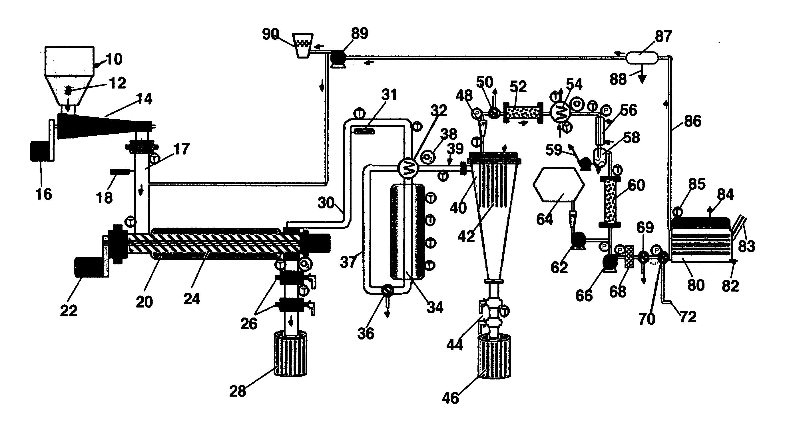
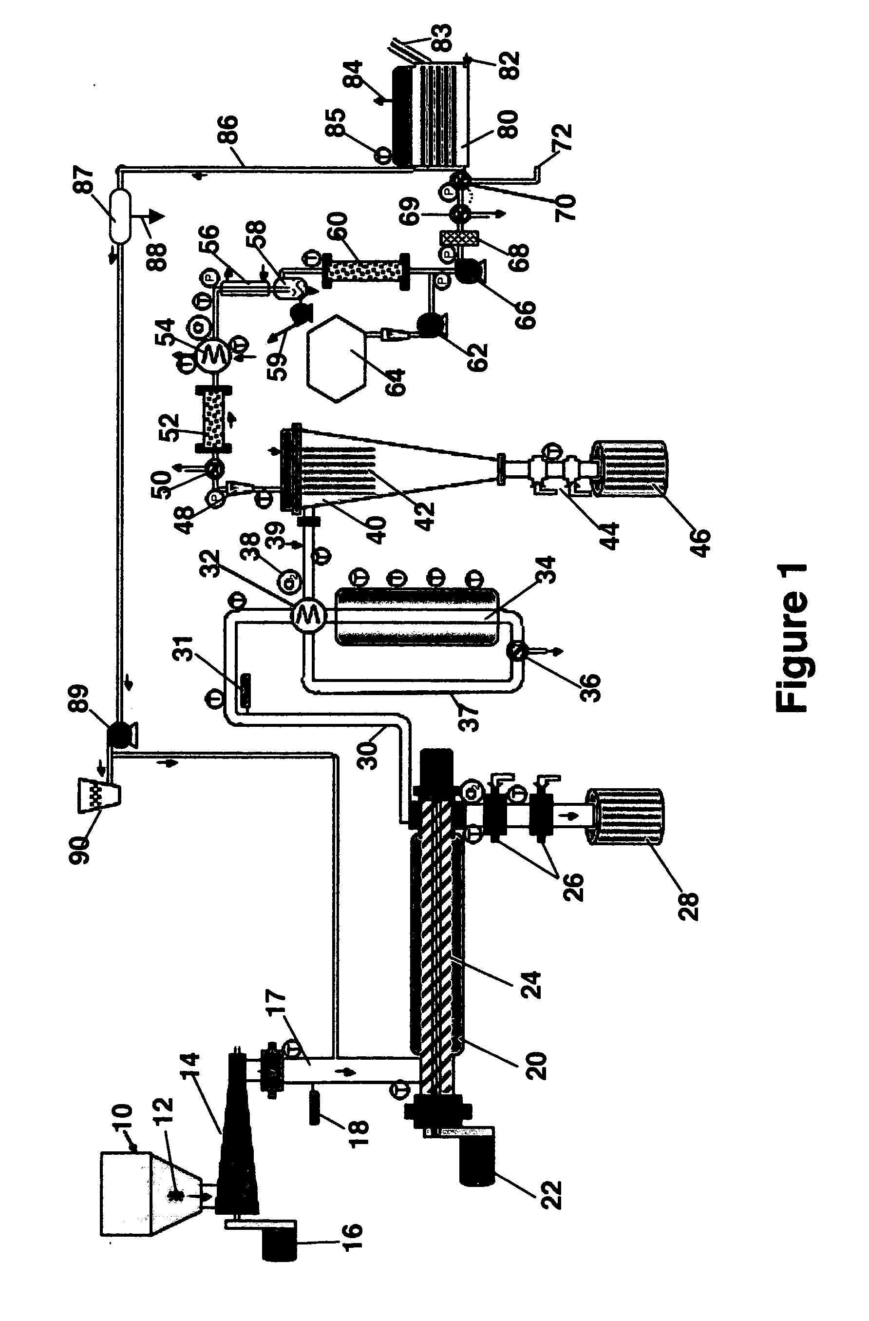
[0039] The pilot plant process configuration used to conduct these tests is described in a recent publication (T. R. Galloway, F. H. Schwartz and J. Waidl, “Hydrogen from S...


PUM

PropertyMeasurementUnit
temperatureaaaaaaaaaa

Abstract

The process of the invention converts carbonaceous feedstock such as coal, hydrocarbon oil, natural gas, petroleum coke, oil shale, carbonaceous-containing waste oil, carbonaceous-containing medical waste, carbonaceous-containing military waste, carbonaceous-containing industrial waste, carbonaceous-containing medical waste, carbonaceous-containing sewage sludge and municipal solid waste, carbonaceous-containing agricultural waste, carbonaceous-containing biomass, biological and biochemical waste, and mixtures thereof into electrical energy without the production of unwanted greenhouse emissions. The process uses a steam / CO2 reformer operating in the exit range of at least 700° to about 1600° C. (1300-2900°0 F.) to convert the carbonaceous feedstock and a greenhouse gas stream into a synthesis gas comprising mostly carbon monoxide and hydrogen that contains poisons and the compounds that poison fuel cells. The syngas is sent to an interface zone to remove these poisons and other fouling compounds that are electrochemically oxidized in an electricity-producing fuel cell into an exit gas comprising carbon dioxide and water.

Description

CROSS REFERENCE TO RELATED APPLICATION [0001] This application claims the benefit of U.S. Provisional Patent Application No. 60 / 749,306 filed Dec. 12, 2005, and is a continuation-in-part of application U.S. Ser. No. 10 / 719,504 filed Nov. 21, 2003, both of which are incorporated herein by reference. The latter application is continuation-in-part of applications U.S. Ser. No. 10 / 602,536 filed Jun. 23, 2003; now U.S. Pat. No. 7,132,183 issued Nov. 7, 2006 (the '183 patent), and U.S. Ser. No. 10 / 184,264 filed Jun. 27, 2002, published as Publication No. 2003 / 0022035 Jan. 30, 2003. This application is related to and contains common subject matter with U.S. Ser. No. 09 / 186,766 filed Nov. 5, 1998; now U.S. Pat. No. 6,187,465 issued Feb. 13, 2001 (the '465 patent), which claims the benefit of U.S. provisional application Ser. No. 60 / 064,692 filed Nov. 7, 1997.FIELD OF INVENTION [0002] This invention relates to gas processes that accomplish without emitting substantial greenhouse gases the co...

Claims


Application Information

Patent Timeline
Patent Type & Authority Applications(United States)
IPC IPC(8): H01M8/06
CPCC10J3/20C10J3/82C10J2200/158C10J2300/1659H01M8/0612H01M8/0668Y02E20/16Y02E50/32Y02E60/50C01B3/38C01B3/56C01B2203/0233C01B2203/0238C01B2203/042C01B2203/0455C01B2203/0485C01B2203/062C01B2203/066C01B2203/148C01B2203/86C10J3/005C10J3/007Y02E20/18Y02E50/30Y02P30/00
Inventor GALLOWAY, TERRY R.
Owner RAVEN SR INC
Why Eureka
Try Eureka