Fuel cell platelet separators having coordinate features

a technology of fuel cell platelet separator and coordinate feature, which is applied in the direction of cell components, final product manufacturing, sustainable manufacturing/processing, etc., can solve the problems of unsatisfactory life, cell power drop, and inability to become widely used in commer

Inactive Publication Date: 2000-04-18
H POWER
View PDF6 Cites 182 Cited by
  • Summary
  • Abstract
  • Description
  • Claims
  • Application Information

AI Technical Summary

Problems solved by technology

Fuel cells for direct conversion of hydrogen or carbonaceous fuels to electricity have shown great theoretical promise, but have not become widely used in commerce because of technical problems and economic reasons.
In the field of hydrogen-air / O.sub.2 fuel cells, power density, that is kilowatts of power generation per pound has been marginal, and the lifetime has been unsatisfactorily short.
Prior art cells have experienced dropoff in power with age due in part to poisoning of catalysts or electrolyte membranes, and the poor distribution of fuel gases internally has led to thermal hot spots leading to cell failure and the like.
The oxidant is O.sub.2 or air, and water is required both for cooling and for humidification of the membrane to keep it from drying out and becoming inefficient or structurally weakened through cracking.
However, the graphite plates must be relatively thick to provide structural integrity and prevent reactant crossover since they are brittle and prone to crack as the cell stacks must be placed under compression to effect intra and inter-cell sealing to prevent reactant leakage.
They have low thermal and electrical conductivity which gives rise to hot spots and dead spots.
They are also difficult to manufacture, especially the gas distribution channels.
This effectively doubles the number of gasketed seals required in a stack thereby decreasing stack reliability and performance.
The aforementioned U.S. Pat. No. 5,316,869 does not offer a solution to graphite plate cell stack design as it is concerned with microprocessor control of a closed loop system external to the stack.

Method used


Image

  • Fuel cell platelet separators having coordinate features
  • Fuel cell platelet separators having coordinate features
  • Fuel cell platelet separators having coordinate features

Examples


Embodiment Construction

The following detailed description illustrates the invention by way of example, not by way of limitation of the principles of the invention. This description will clearly enable one skilled in the art to make and use the invention, and describes several embodiments, adaptations, variations, alternatives and uses of the invention, including what we presently believe are the current best modes of carrying out the invention.

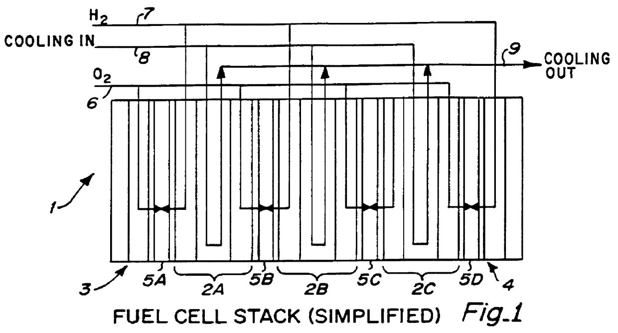
FIG. 1 shows in simplified (schematic) cross section a fuel cell stack 1 of this invention employing a plurality of multi-platelet bipolar separators 2A, B, C and a pair of cathode and anode unipolar end separators 3, 4 respectively. Proton exchange Electrode Membrane Assemblies (EMAs) 5A, B, C, and D are disposed between the separators as shown. Air and / or O.sub.2 is inlet via manifold system 6, H.sub.2 and / or other fuel inlet via manifold 7, and cooling / humidification water is inlet at 8 and outlet at 9.

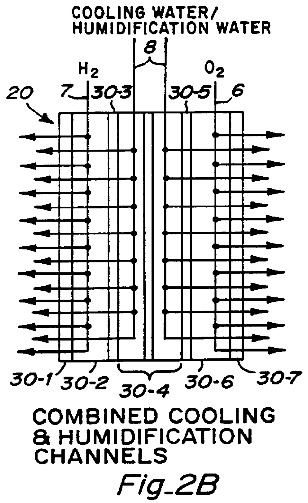
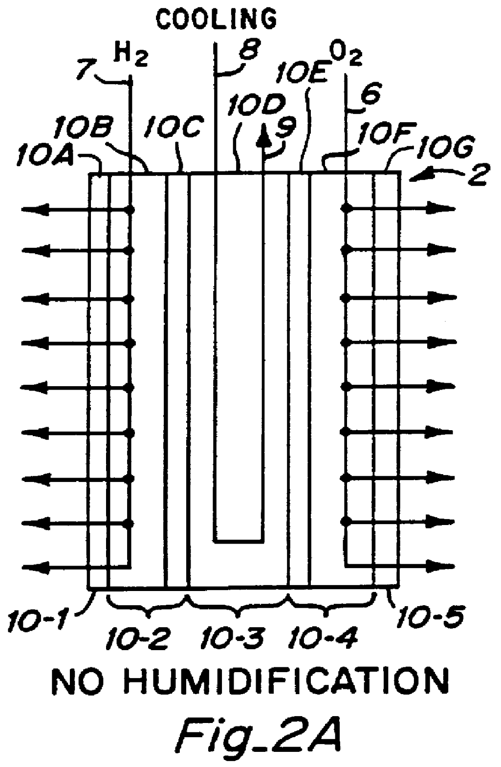
FIG. 2A and 2B show in schematic section view the constructio...


PUM

PropertyMeasurementUnit
voltagesaaaaaaaaaa
weightaaaaaaaaaa
thickaaaaaaaaaa

Abstract

PCT No. PCT/US95/13325 Sec. 371 Date Sep. 28, 1997 Sec. 102(e) Date Sep. 28, 1997 PCT Filed Oct. 10, 1995 PCT Pub. No. WO96/12316 PCT Pub. Date Apr. 25, 1996Fuel cell stacks comprising stacked separator/membrane electrode assembly fuel cells in which the separators comprise a series of thin sheet platelets, having individually configured serpentine micro-channel reactant gas humidification active areas and cooling fields therein. The individual platelets are stacked with coordinate features aligned in contact with adjacent platelets and bonded to form a monolithic separator. Post-bonding processing includes passivation, such as nitriding. Preferred platelet material is 4-25 mil Ti, in which the features, serpentine channels, tabs, lands, vias, manifolds and holes, are formed by chemical and laser etching, cutting, pressing or embossing, with combinations of depth and through etching preferred. The platelet manufacturing process is continuous and fast. By employing CAD based platelet design and photolithography, rapid change in feature design can accommodate a wide range of thermal management and humidification techniques. One hundred H2-O2/PEM fuel cell stacks of this IFMT platelet design will exhibit outputs on the order of 0.75 kW/kg, some 3-6 times greater than the current graphite plate PEM stacks.

Description

This invention relates to fuel cells, and more particularly to fuel cells constructed of stacked platelets having integrated fluid management technology (IFMT), and to methods of manufacture and operation of the IFM cells. A particular embodiment employing the principles of this invention is ahydrogen-air / O.sub.2 fuel cell employing multiple separators formed of bonded platelets of titanium. niobium, copper, stainless steel, aluminum or plastic having individually configured micro-channel reactant gas, coolant and humidification zones therein, which cells operate in the range of about 50 to 150.degree. C., and have an output of on the order of0.25-1.0 kW per Kg and 0.5-1.0 kW / L for use in both stationary and mobile power generation applications in open or closed loop configurations. The IFM platelet and separator design can be adjusted throughout the fuel cell stack to accommodate varying thermal management and humidification requirements within each cell.Fuel cells for direct conve...

Claims


Application Information

Patent Timeline
Patent Type & Authority Patents(United States)
IPC IPC(8): F28F3/00F28F3/04F28D9/00H01M8/24H01M8/02H01M8/04H01M8/00
CPCF28D9/0075F28F3/048H01M8/0202H01M8/0206H01M8/0228H01M8/0245H01M8/0247H01M8/0263H01M8/0267H01M8/241F28F3/04Y02E60/50F28F2260/02H01M8/0208H01M8/021H01M8/0234H01M8/0256H01M8/04029H01M8/04074H01M8/04119H01M2300/0082F28F2250/102Y02P70/50H01M8/2483H01M8/242H01M8/2404H01M8/026
Inventor SPEAR, JR., REGINALD G.MUEGGENBURG, H. HARRYHODGE, REX
Owner H POWER
Why Eureka
Try Eureka