

Vehicle Deceleration Warning System
a technology of vehicle deceleration and warning system, which is applied in the direction of vehicle components, signalling/lighting devices, optical signalling, etc., can solve the problems of dangerous following of vehicles
Inactive Publication Date: 2009-10-22
AULT SCOTT T
View PDF4 Cites 73 Cited by
- Summary
- Abstract
- Description
- Claims
- Application Information
AI Technical Summary
Benefits of technology
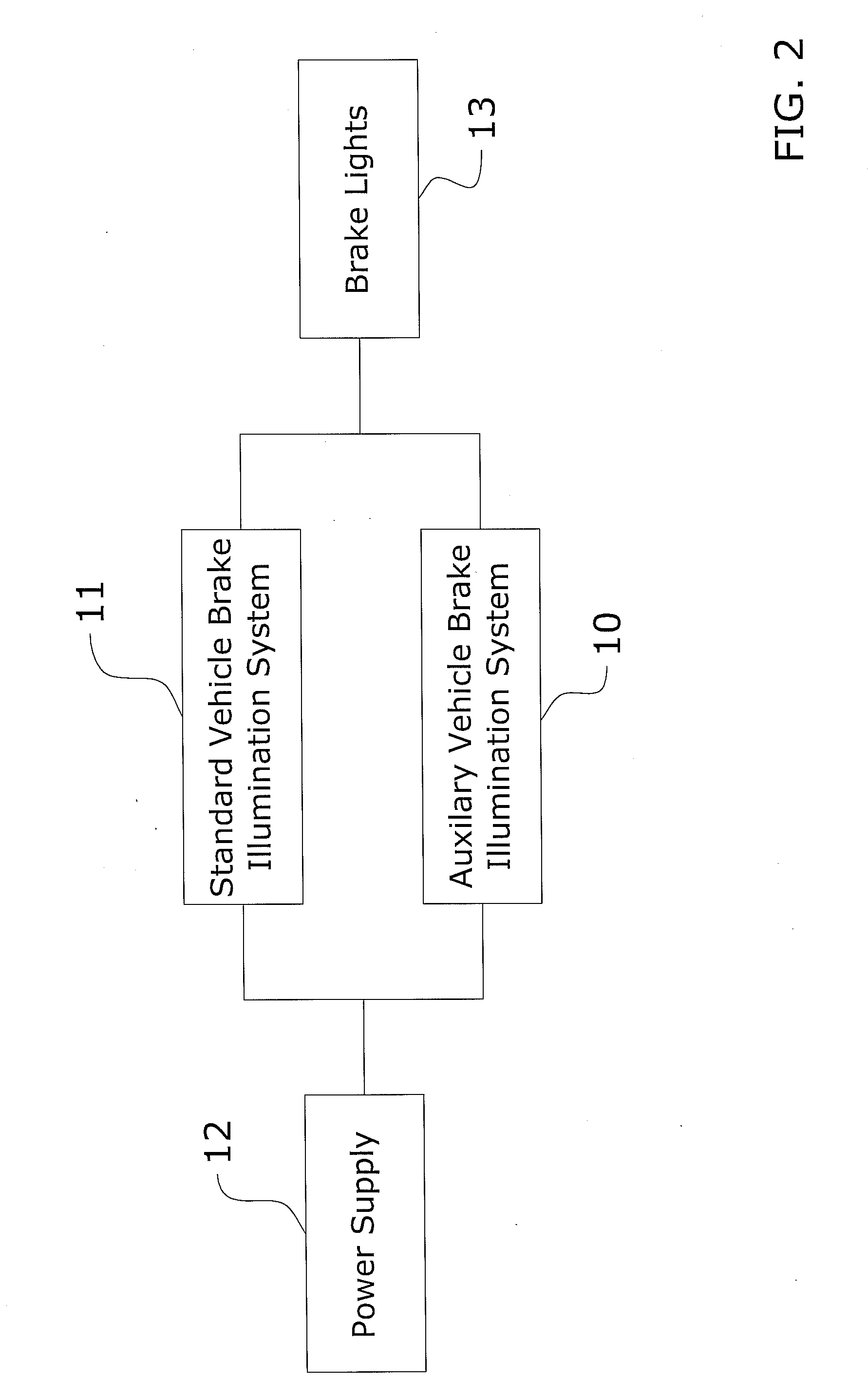
"The present invention is a vehicle deceleration warning system that uses an accelerometer and a control unit to activate brake lights based on the vehicle's speed and deceleration rate. The system can be installed separately from a standard brake illumination system and can be used on any type of vehicle. It includes indicator lights to alert the operator of the vehicle if the brake lights are on from exceeding the speed threshold or the deceleration threshold. The system operates automatically and does not require any changes in the driver's habits. It measures the deceleration of the vehicle using an accelerometer and activates the brake lights if the measured g-forces reach a certain threshold. The technical effects of this invention include efficient warning of decelerating or slow-moving leading vehicles, improved safety on the road, and the ability to install the system on any type of vehicle."
Problems solved by technology
This can be very dangerous for following vehicles in that it may not be apparent that the leading vehicle is slowing down.
Method used
View moreImage
Smart ImageViewing Examples

Examples
new embodiment
E. Operation of New Embodiment
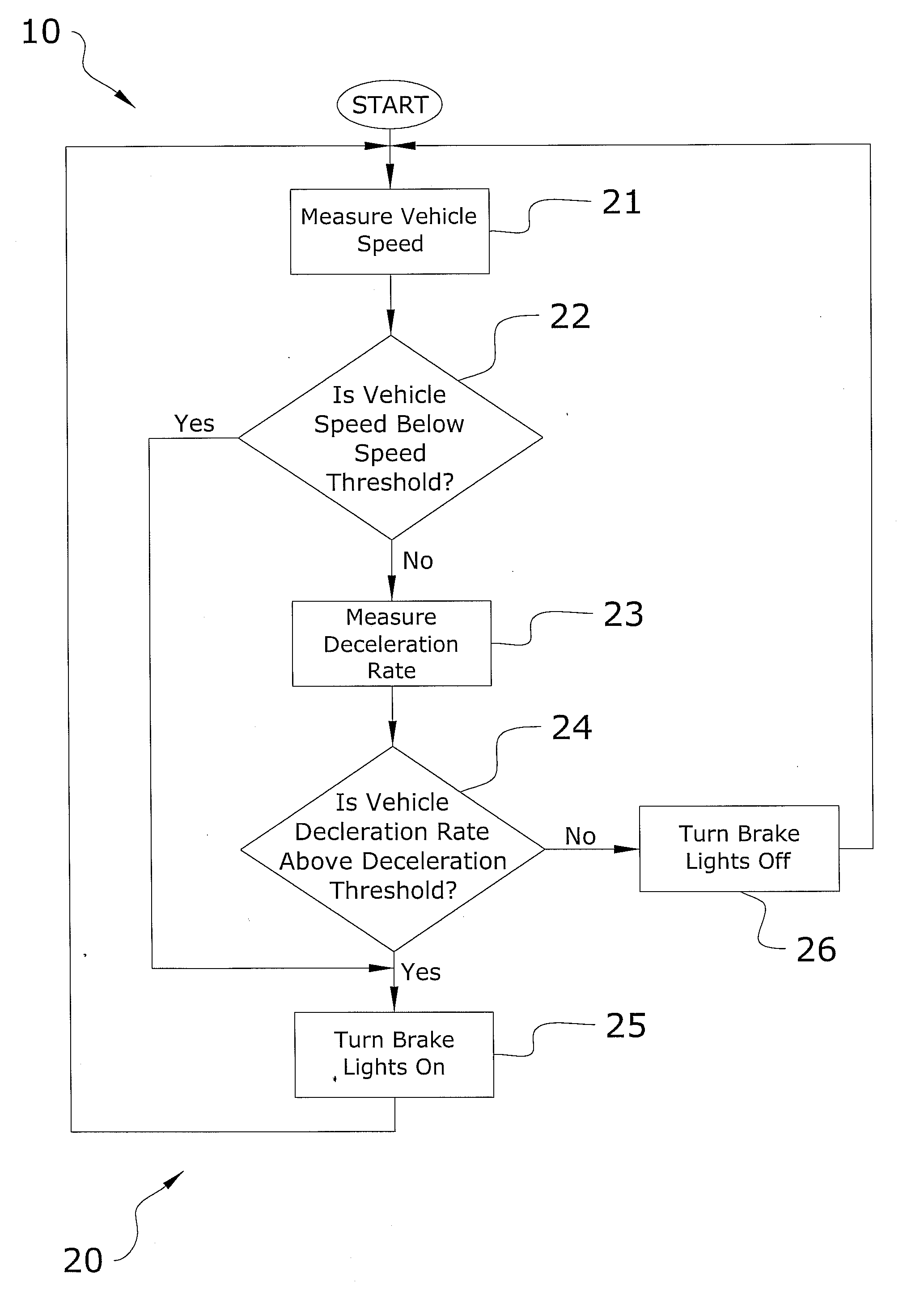
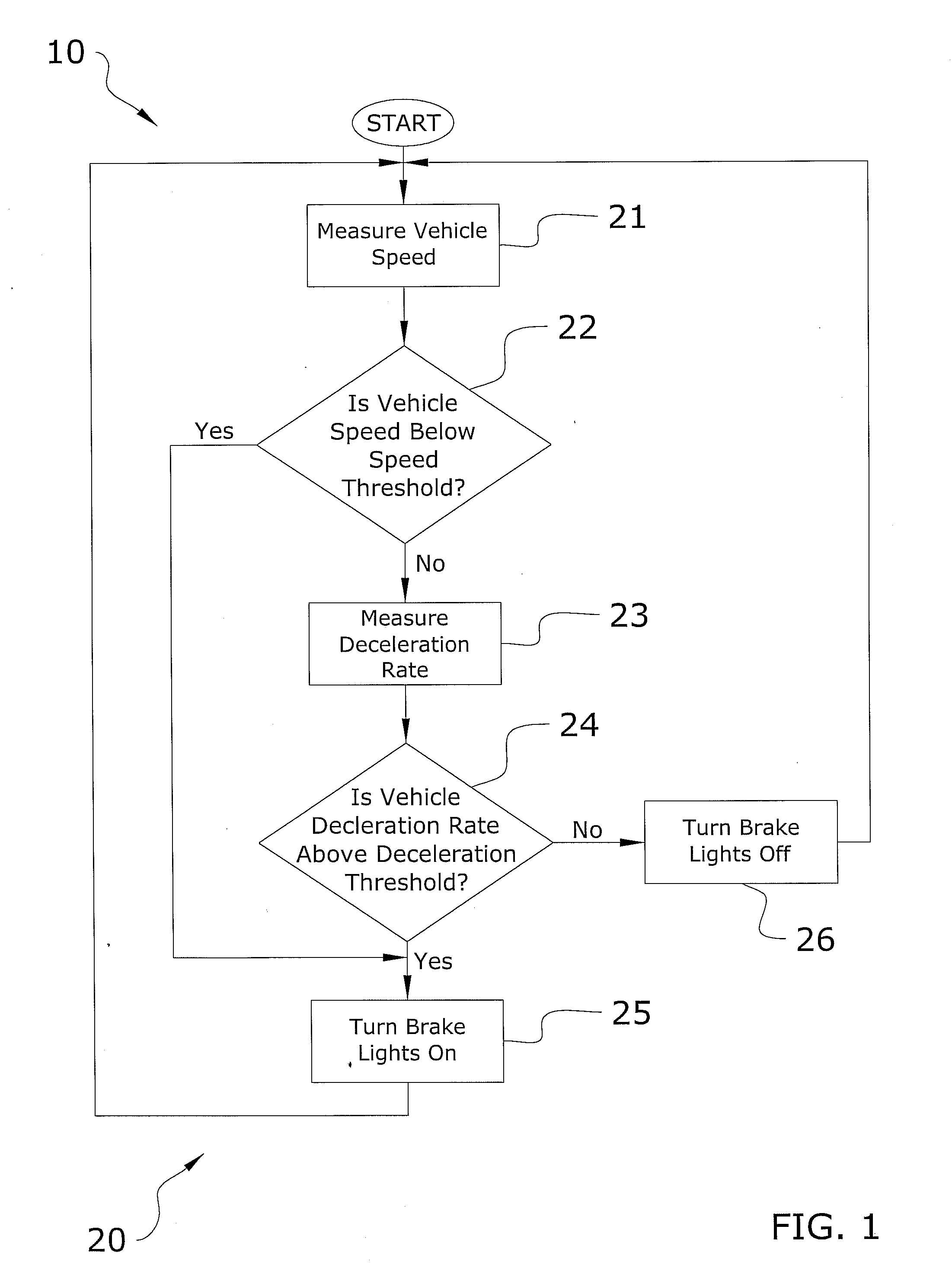
[0060]In use, when the engine is turned on, the brake lights 13 are automatically activated. As the vehicle is accelerated and the speed threshold is exceeded (i.e. vehicle traveling faster than speed threshold), the brake lights 13 are deactivated and thus turn off. When the vehicle slows down to a pace slower than the speed threshold, the brake lights 13 and the first indicator 17 will once again illuminate. This is determined by using the accelerometer 19 to measure the g-force of the vehicle. Once the g-force of the vehicle exceeds the pre-defined threshold, the brake lights 13 turn on. It is appreciated that the accelerometer 19 may be used in addition to or in place of the speed sensor 14.
Login to View More PUM
 Abstract
A vehicle deceleration warning system for efficiently warning following vehicles of a decelerating or slow moving leading vehicle. The vehicle deceleration warning system generally includes an accelerometer, a control unit electrically connected to the accelerometer, a brake light relay electrically connected to the control unit and at least one brake light electrically connected to the brake light relay. The control unit activates the brake light relay to illuminate the at least one brake light depending upon a measurement taken by the accelerometer.
Description
CROSS REFERENCE TO RELATED APPLICATIONS[0001]I hereby claim benefit under Title 35, United States Code, Section 120 of U.S. patent application Ser. No. 12 / 107,111 filed Apr. 22, 2008. This application is a continuation in-part of the Ser. No. 12 / 107,111 application. The Ser. No. 12 / 107,111 application is currently pending. The Ser. No. 12 / 107,111 application is hereby incorporated by reference into this application.STATEMENT REGARDING FEDERALLY SPONSORED RESEARCH OR DEVELOPMENT[0002]Not applicable to this application.BACKGROUND OF THE INVENTION[0003]1. Field of the Invention[0004]The present invention relates generally to a vehicle deceleration warning system and more specifically it relates to a vehicle deceleration warning system for efficiently warning following vehicles of a decelerating or slow moving leading vehicle.[0005]2. Description of the Related Art[0006]Any discussion of the related art throughout the specification should in no way be considered as an admission that suc...
Claims
Login to View More Application Information
Patent Timeline
 Patent Type & AuthorityApplications(United States)
IPC IPC(8): B60Q1/50
CPCB60Q1/445B60Q1/44
InventorAULT, SCOTT T.
OwnerAULT SCOTT T