
Tonsil forceps

a technology of tonsils and forceps, applied in the field of medical forceps, can solve the problems of undesirable fragmentation of tonsils during resection, difficult to grasp tonsils,

Inactive Publication Date: 2009-10-22
WOHL DANIEL L
View PDF17 Cites 5 Cited by
  • Summary
  • Abstract
  • Description
  • Claims
  • Application Information

AI Technical Summary

Benefits of technology

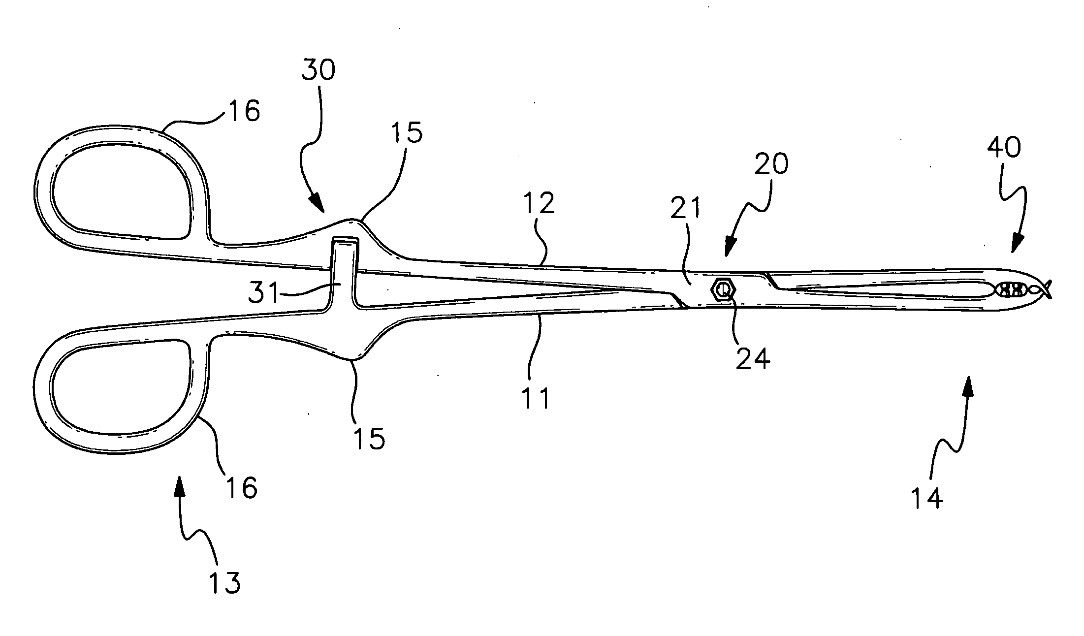
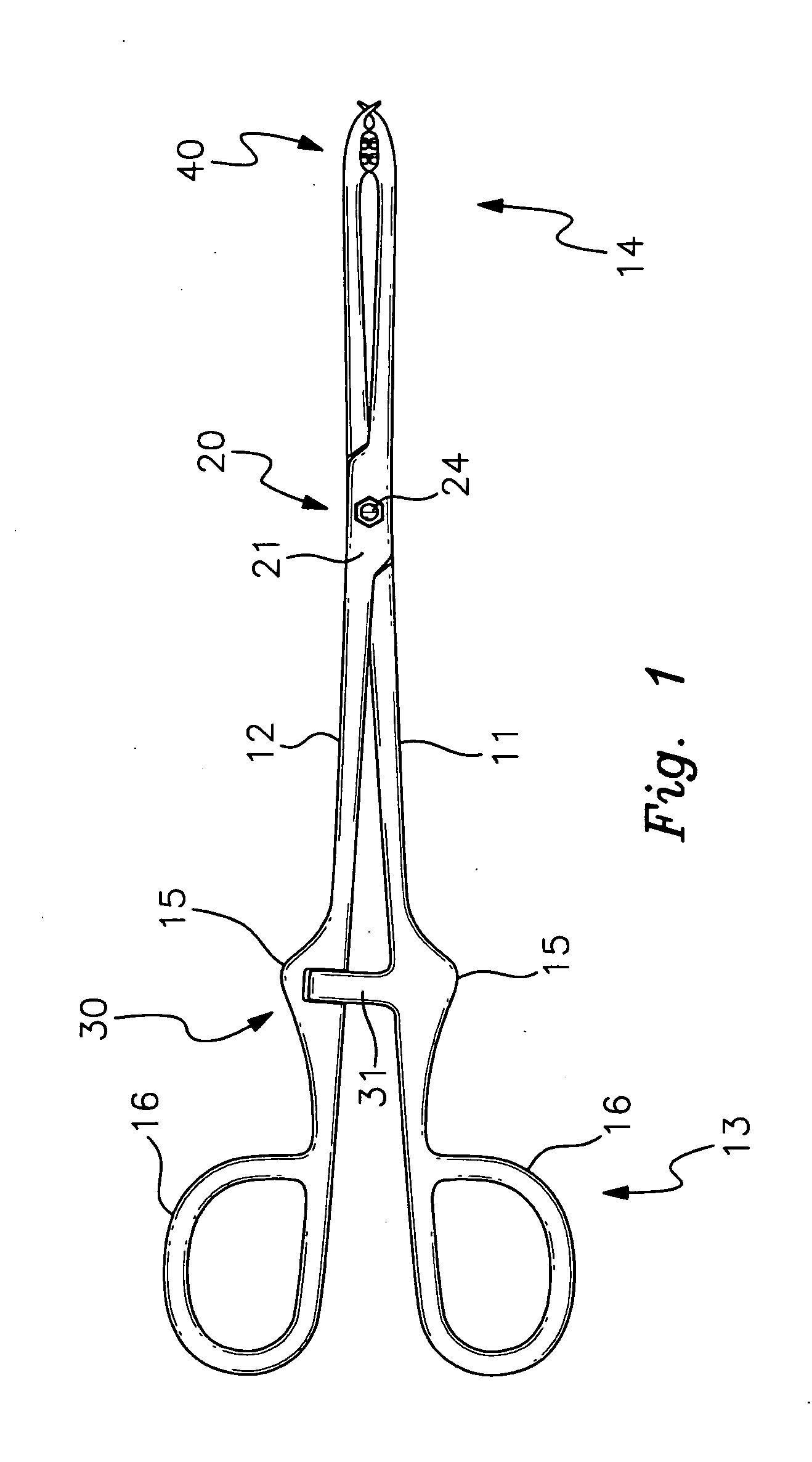
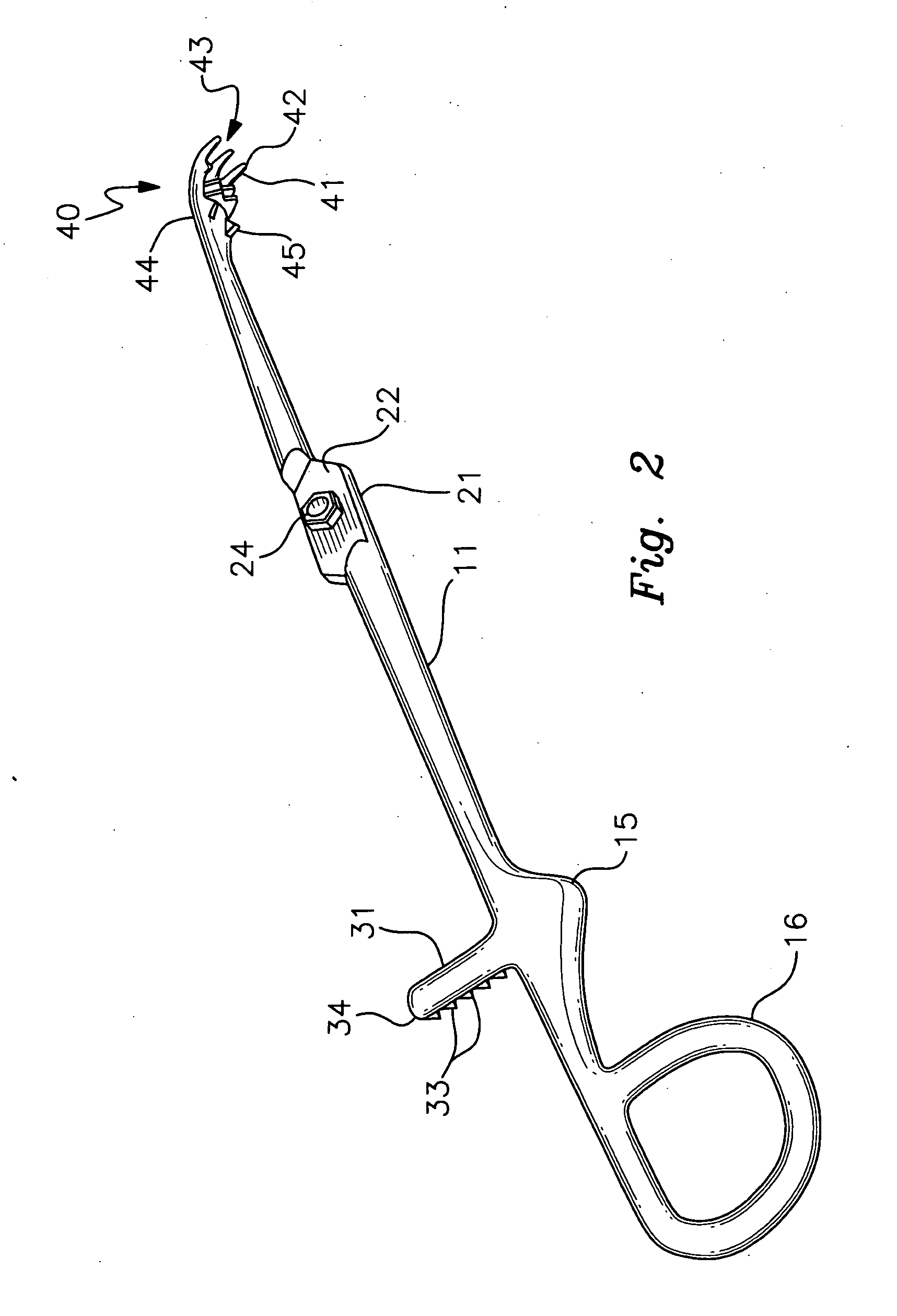
[0006]The invention is a tonsil forceps comprising first and second intersecting and pivoting arm members, the arm members being joined by pivoting connection means at an intermediate point such that the distal end of the forceps can be closed for grasping and opened for release in a scissoring manner by relative movement of the proximal ends toward and away from each other, respectively. Releasable locking means for securing the forceps in multiple locked positions are provided, such as for example a ratchet-type mechanism. Finger loops are provided on the proximal ends of the arm members. Each of the distal ends of the arm members comprises grasping means for securing a tonsil, each grasping means comprising a palm-like curved portion and a set of inwardly curved, blunt tipped, finger-like tine members extending generally inwardly from the palm-like curved portions, wherein the sets of finger-like tine members of one distal end pass between but do not contact the finger-like tine members of the other distal end when the forceps are closed. In at least one of the locked positions, the tips on one set of the finger-like tines do not cross the tips of the other set of finger-like tines. The grasping means further comprise inwardly facing projection members, such as raised ridges, blunted teeth, posts, nubs or the like, are located on the interior sides of the palm-like curved portions. The projection members are non-contacting with each other even in the maximum closed forceps position.

Problems solved by technology

Often the tonsils are partially embedded within the muscles and fascia, such that grasping the tonsil is difficult.
The current style forceps used for this task tend to bite, stab or cut the tonsil during this grasping operation, resulting in undesirable fragmentation of the tonsil during the resection.

Method used


Image

  • Tonsil forceps
  • Tonsil forceps
  • Tonsil forceps

Examples


Embodiment Construction

[0012]With reference to the drawings, the invention will now be described in detail with regard for the best mode and the preferred embodiment. In a most general sense, the invention is a tonsil forceps for grasping or pulling a tonsil so as to separate it from the surrounding mucosa, muscle and fascia, the structure of the grasping means being such that the tonsil is cradled rather than stabbed or cut by the grasping means during removal, and therefore remains intact as opposed to being fragmented during the resection procedure. The tonsil forceps may be realized in various embodiments.

[0013]The tonsil forceps comprise a first intersecting arm member 11 and a second intersecting arm member 12, each having a distal end 13 and a proximal end 14. The arm members 11 and 12 are connected by means 20 for pivoting the arm members 11 and 12, such that the distal ends 13 of the arm members 11 and 12 can be closed and opened by bringing together or spreading apart the arm member proximal end...


PUM


Abstract

A tonsil forceps having first and second intersecting and pivoting arm members, releasable locking members for securing the forceps in multiple positions and sets of inwardly curved, blunt tipped, finger-like tine members, wherein the sets of tine members do not contact each other when the forceps are closed. In at least one of the locked positions, the tips on one set of the finger-like tines do not cross the tips of the other set of finger-like tines. The finger-like tines extend from a palm-like curved portion of each arm member, and inwardly facing non-sharp projection members, such as raised ridges, blunted teeth or the like are located on the interior sides of the palm-like curved portions. The projecting members are non-contacting with each other even in the maximum closed forceps position.

Description

[0001]This application claims the benefit of U.S. Provisional Patent Application Ser. No. 61 / 069,942, filed Mar. 18, 2008.BACKGROUND OF THE INVENTION[0002]This invention relates generally to the field of medical forceps, and more particularly to such forceps that are lockable in multiple indexed closure positions and that possess distal end finger-like projections.[0003]Forceps are handheld instruments in the form of tongs or pincers used to grasp, compress or pull body parts, tissue, organs, teeth, etc. A typical forceps comprises a pair of pivotally joined elongated arm members, the proximal ends of the arms being provided with finger holes for manipulating the instrument and the distal ends being provided with grasping structures suited for particular purposes, such as finger-like extensions, sharp teeth, blades, curved members, concave members, etc. Many forceps are provided with releasable locking means, such as for example a pair of opposing toothed bar members, one mounted on...

Claims


Application Information

Patent Timeline
Patent Type & Authority Applications(United States)
IPC IPC(8): A61B17/26
CPCA61B17/24A61B2017/2837A61B17/282A61B17/26A61B17/2833
Inventor WOHL, DANIEL L.
Owner WOHL DANIEL L
Learn More