
Medical ultrasound instrument with articulated jaws

Active Publication Date: 2013-05-21
TYCO HEALTHCARE GRP LP
View PDF86 Cites 295 Cited by
  • Summary
  • Abstract
  • Description
  • Claims
  • Application Information

AI Technical Summary

Benefits of technology

The present invention is a forceps that includes a housing, a shaft assembly, an end effector assembly, a trigger assembly, a rotating assembly, an articulator, and a waveguide assembly. The forceps can generate a mechanical vibration in response to energy transmitted from an energy source, such as a smart battery, to treat tissue. The forceps have articulating members and clamping members that can move the pair of jaw members between unapproximated and approximated configurations. The articulating members are operably coupled to the jaw members and are positioned along an outer surface of ball bearings to enable longitudinal translation of the end effector assembly. The waveguide assembly is positioned within the shaft assembly and is at least partially positioned within one or both of the jaw members. The waveguide assembly includes a waveguide and an ultrasonic treatment member that can transmit the mechanical vibration to treat tissue. The trigger assembly is operably coupled to the housing and can activate the forceps to transmit energy to the transducers. The rotating assembly can rotate the shaft assembly and the end effector assembly upon rotation thereof. The articulator is operably coupled to the articulating members and moves in response to movement of the articulator. This invention provides a forceps that can efficiently treat tissue with precision and ease of use.

Problems solved by technology

An endoscopic forceps that utilizes ultrasound and is configured for use with small cannulas (e.g., cannulas less than five millimeters) may present design challenges for a manufacturer of endoscopic instruments.

Method used


Image

  • Medical ultrasound instrument with articulated jaws
  • Medical ultrasound instrument with articulated jaws
  • Medical ultrasound instrument with articulated jaws

Examples


Embodiment Construction

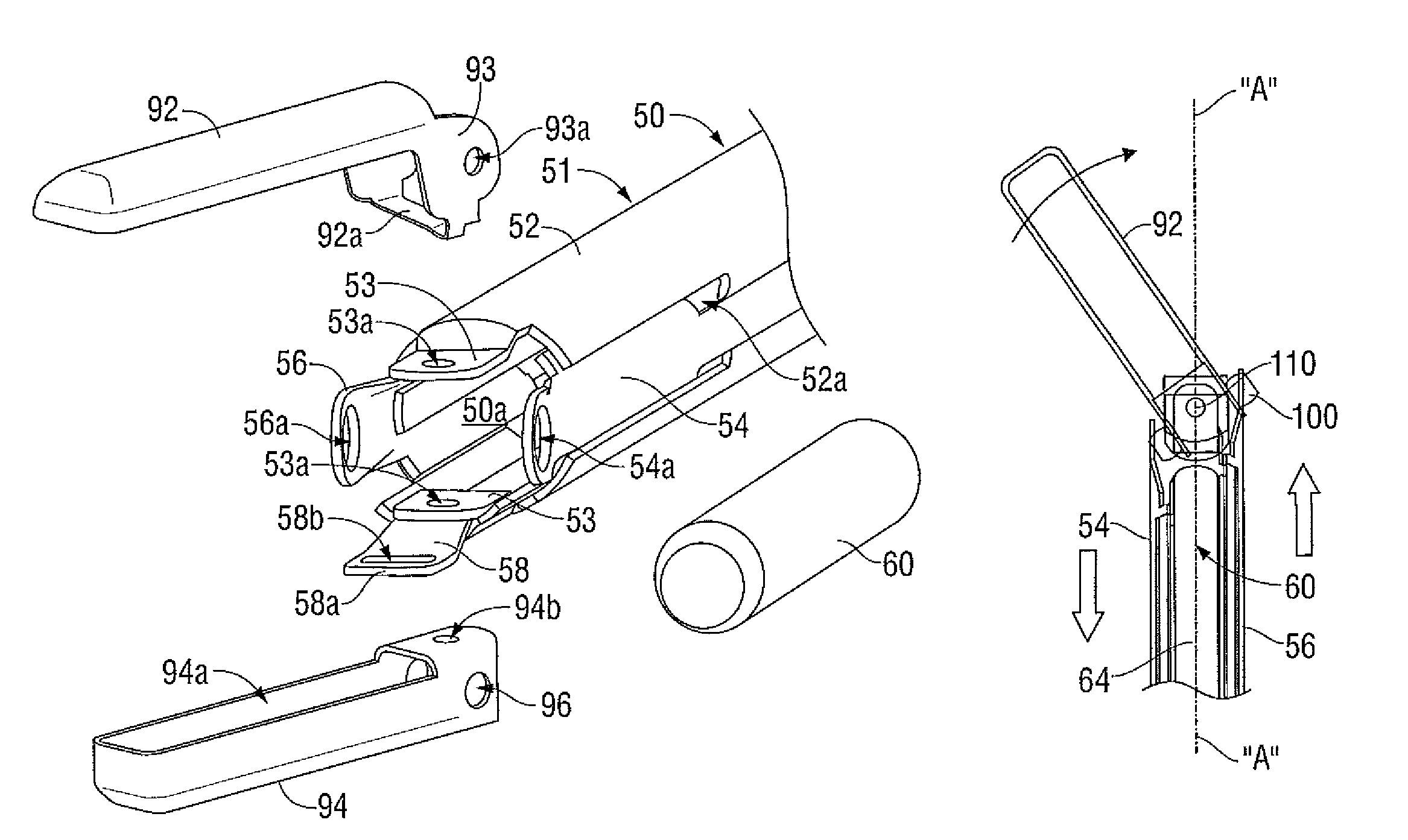
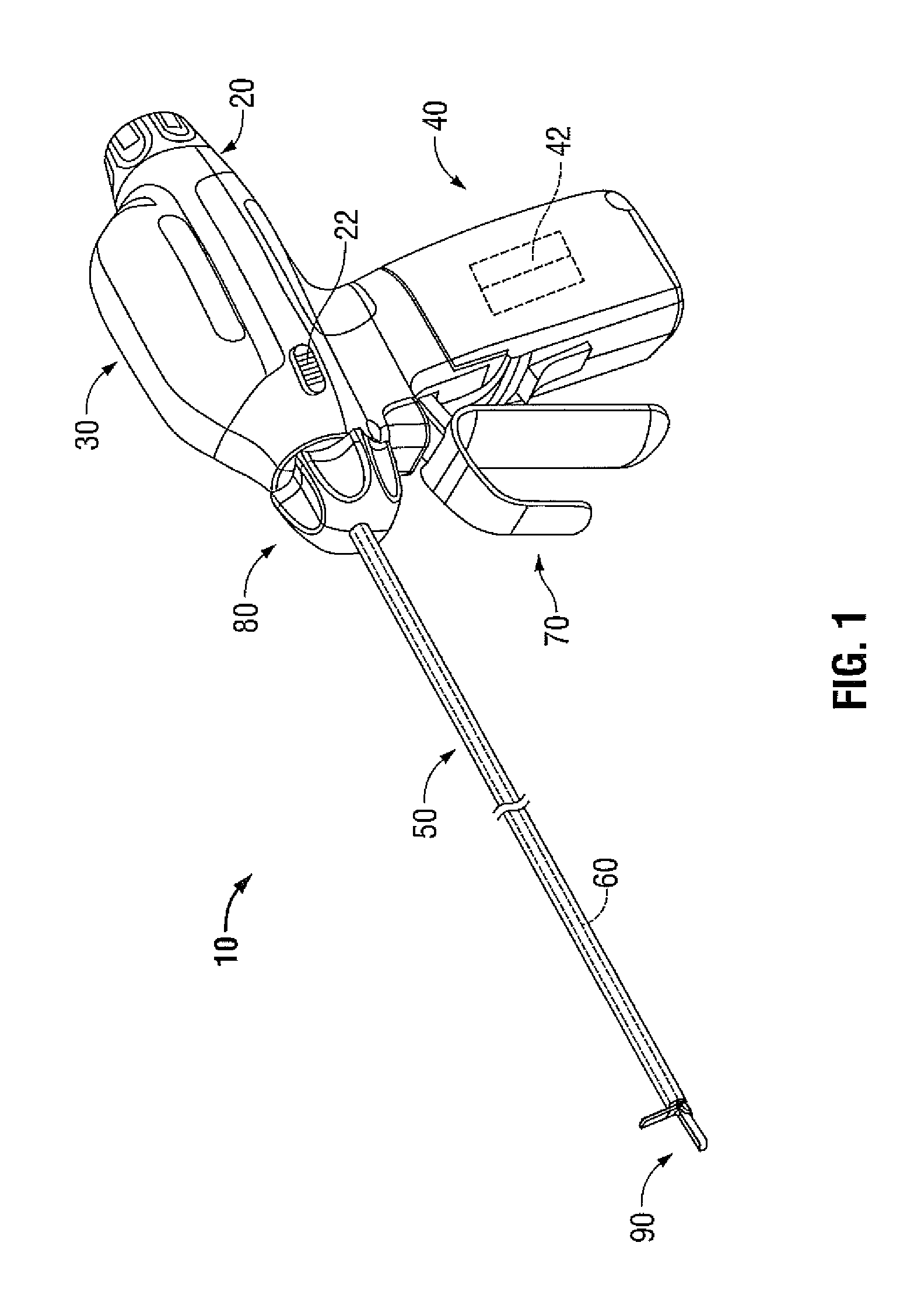
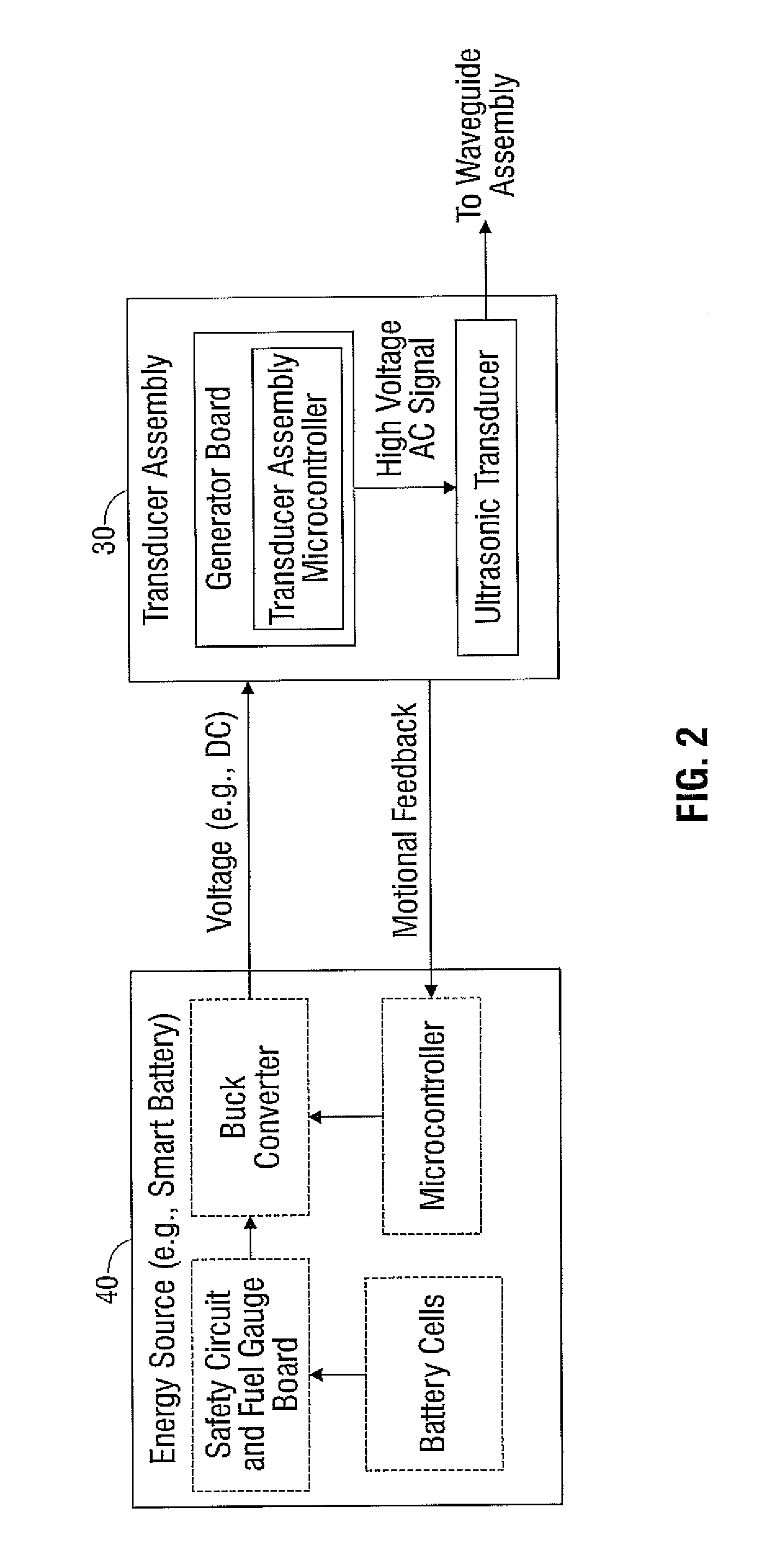
[0024]Detailed embodiments of the present disclosure are disclosed herein with reference to the accompanying drawings; however, the disclosed embodiments are merely examples of the disclosure, which may be embodied in various forms. As shown in the drawings and as described throughout the following description, and as is traditional when referring to relative positioning on an object during proper use, the term “proximal” refers to the end of the apparatus that is closer to the user and the term “distal” refers to the end of the apparatus that is farther from the user. In the following description, well-known functions or constructions are not described in detail to avoid obscuring the present disclosure in unnecessary detail. Therefore, specific structural and functional details disclosed herein are not to be interpreted as limiting, but merely as a basis for the claims and as a representative basis for teaching one skilled in the art to variously employ the present disclosure in v...


PUM


Abstract

A forceps includes a housing, a shaft assembly, an end effector assembly, and a waveguide assembly. The housing has one or more transducers that generate a mechanical vibration in response to energy transmitted thereto from an energy source. The shaft assembly extends from the housing and includes one or more articulating and clamping members and a longitudinal axis defined therethrough. The end effector assembly is disposed at a distal end of the shaft assembly and includes a pair of opposing jaw members pivotable between approximated and unapproximated configurations in response to movement of the one or more clamping members. The articulating members articulate the jaw members relative to the longitudinal axis of the shaft assembly. The waveguide assembly is positioned within the shaft assembly and receives the mechanical vibration generated by the transducer. The waveguide assembly is positionable within one or both of the jaw members.

Description

BACKGROUND[0001]1. Technical Field[0002]The present disclosure relates to endoscopic surgical instruments. More particularly, the present disclosure relates to an endoscopic forceps that utilizes ultrasound to seal and cut tissue.[0003]2. Background of the Related Art[0004]As an alternative to open instruments for use with open surgical procedures, many modern surgeons use endoscopes and endoscopic electrosurgical apparatuses (e.g., endoscopic or laparoscopic forceps) for remotely accessing organs through smaller, puncture-like incisions. These instruments are particularly suited for use in minimally invasive procedures, such as endoscopic or laparoscopic procedures where patients tend to benefit from less scarring, less pain, and reduced healing time. Typically, the endoscopic forceps is inserted into the patient through one or more various types of cannulas or access ports (typically having an opening that ranges from about five millimeters to about fifteen millimeters) that has b...

Claims


Application Information

Patent Timeline
Patent Type & Authority Patents(United States)
IPC IPC(8): A61B17/32
CPCA61B17/320092A61B18/00A61B2017/00734A61B2017/2927A61B2017/2947A61B2017/2933A61B2017/2939A61B2017/2929A61B2017/320094A61B2017/320095A61B2017/320093
Inventor BALANEV, ANDREYMARTSINOVSKIY, GEORGYMISUCHENKO, IGORISRUIN, ALEXEYVASIL'EV, VLADIMIR
Owner TYCO HEALTHCARE GRP LP
Learn More