Eureka AIR delivers breakthrough ideas for toughest innovation challenges, trusted by R&D personnel around the world.

Medical ultrasonic imaging pulse transmission method

a technology of ultrasonic imaging and pulse transmission, applied in the field of medical ultrasonic imaging pulse transmission method, can solve the problems of affecting the sensitivity of second harmonic signals

Inactive Publication Date: 2004-01-27
SIEMENS MEDICAL SOLUTIONS USA INC
View PDF10 Cites 65 Cited by
  • Summary
  • Abstract
  • Description
  • Claims
  • Application Information

AI Technical Summary

Benefits of technology

The patent describes a method for improving the performance of ultrasonic imaging systems by maintaining the power level of each transducer element in a set of pulses. This is achieved by using larger apertures for the larger amplitude pulses and smaller apertures for the smaller amplitude pulses. The method ensures that the echo signals from the pulses have the desired amplitudes to cancel out the desired frequencies. By doing so, the non-linear effects of the transmitter are removed, and the problems of even-order non-linearities are addressed. The method also ensures that the phase of the smaller amplitude pulses is different from the phase of the larger amplitude pulses, which further improves the performance of the system.

Problems solved by technology

The technique described by Brock-Fisher et al. suffers from degraded sensitivity to second harmonic signals.
Such a loss in signal may be unacceptable, especially since the non-linear signals may be weak to begin with.
Non-linear elements of the transmitter circuitry and the transducer can make this quite difficult to achieve.
For example, diodes in the transmitter circuitry may cause problems since they often result in a fixed voltage drop.
Attempts to correct for these non-linearities can be quite difficult, since these non-linearities can vary with different transmit voltages.

Method used


Image

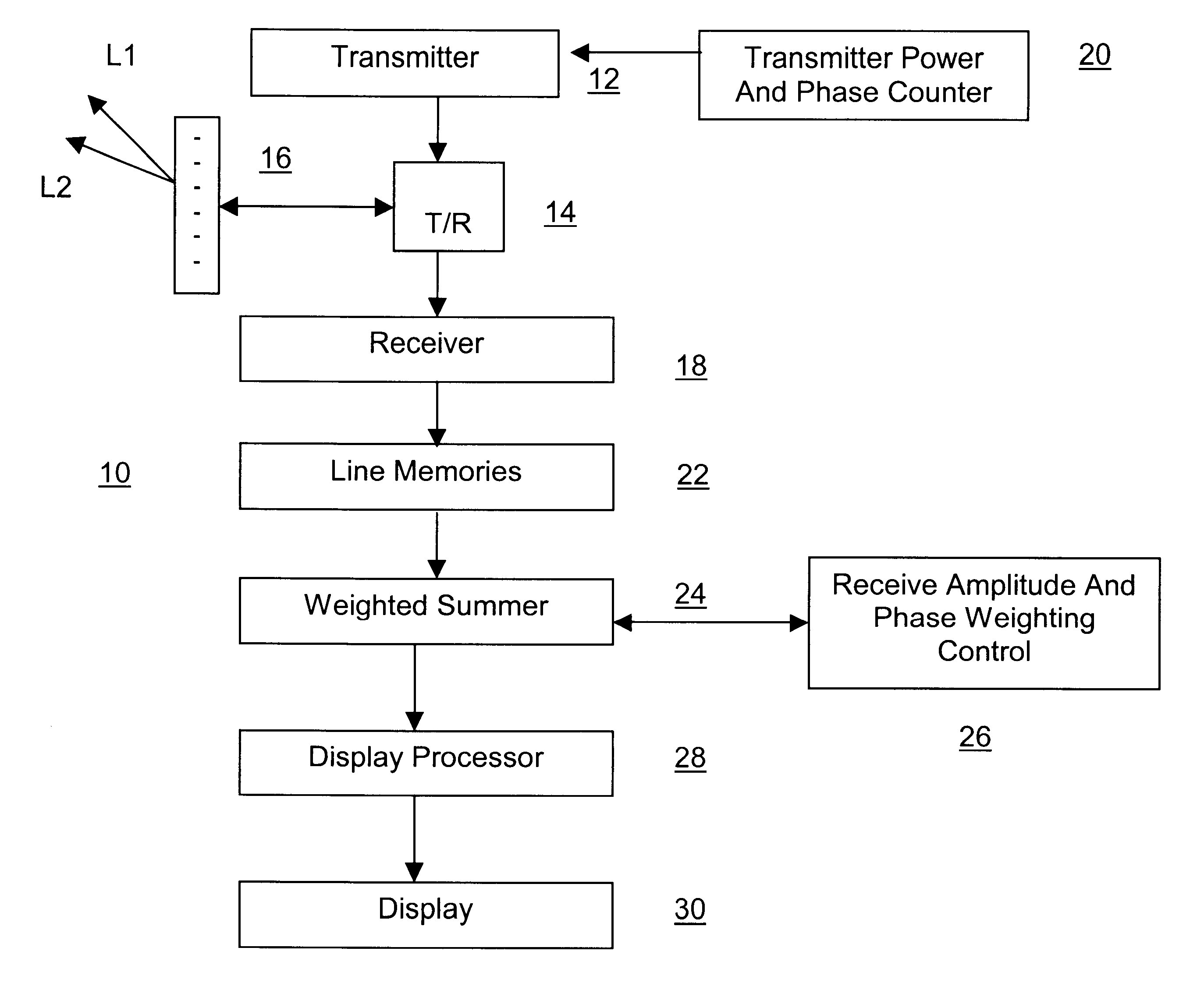
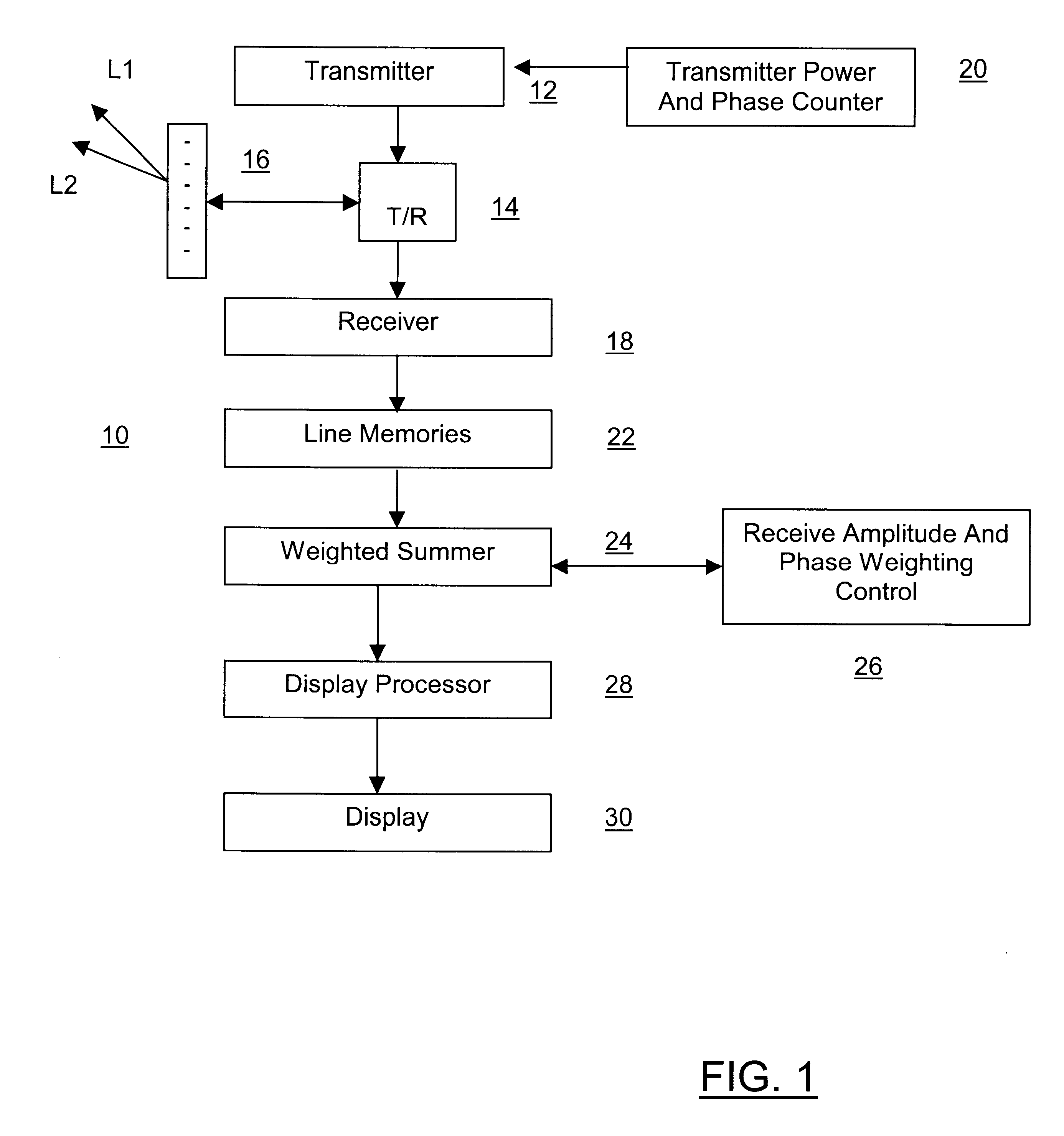
  • Medical ultrasonic imaging pulse transmission method
  • Medical ultrasonic imaging pulse transmission method
  • Medical ultrasonic imaging pulse transmission method

Examples


example 2

of FIG. 7 is closely related to Example 1, but in this case the first subaperture for the first positive-polarity pulse includes all even-numbered transducer elements, and the second subaperture for the second positive-polarity pulse includes all odd-numbered transducer elements.

examples 3 , 4 and 5

Examples 3, 4 and 5 relate to a transducer array having 16 transducer elements. As shown in Example 3, transducer elements are grouped in pairs, with adjacent pairs of transducer elements active in either, the first or second subaperture for the positive-polarity pulses, and all of the transducer elements active for the negative-polarity pulse.

example 4

is similar to Example 3, except that the transducer elements are grouped into groups of four, with each group of four transducer elements active in one or the other of the first and second subapertures.

It is not essential that the same number of transducer elements be included in the first and second subapertures. For example, in Example 5 the first subaperture for the first positive-polarity pulse includes six transducer elements (1, 2, 13-16), while the second subaperture for the second positive-polarity pulse includes 10 transducer elements (3-12). In general, any desired subset of transducer elements can be used for the first subaperture, and the remaining subset of elements can be used for the second subaperture. Whether or not the two subapertures are equal, it is preferred that the two subapertures when added together equal the full aperture. The disadvantage of making the two subapertures unequal in size is that this will reduce the sensitivity of the approach to cubic funda...


PUM


Abstract

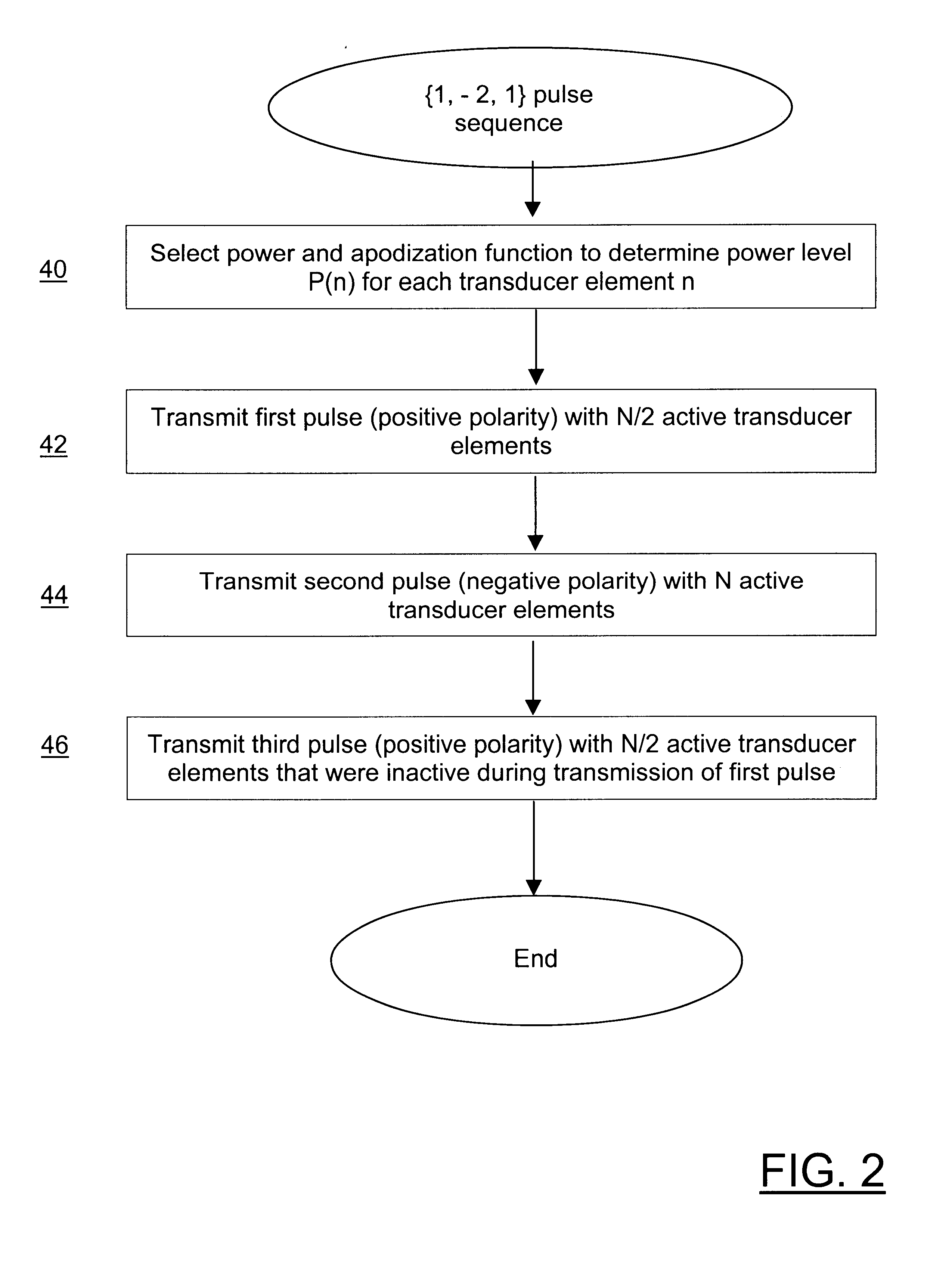
A medical ultrasound imaging pulse transmission method transmits at least three pulses, including at least two pulses of different amplitude and at least two pulses of differing phase. The larger-amplitude pulse is transmitted with a larger aperture and the smaller-amplitude pulses are transmitted with respective smaller subapertures. The subapertures are arranged such that the sum of the subapertures used for the smaller-amplitude pulses is equal to the aperture used for the larger-amplitude pulse. In this way, pulses of differing amplitudes are obtained without varying the power level of individual transducer elements, and precise control over pulse amplitude is provided.

Description

This invention relates generally to medical ultrasonic imaging, and more specifically to improved methods for transmitting pulses with desired power levels.Brock-Fisher et al. (U.S. Pat. No. 5,577,505) describe several methods for isolating non-linear responses from contrast agent and tissue. In one method, multiple pulses are fired along a line, where one pulse uses the entire transducer aperture. The aperture is then divided into two or more subapertures, and other pulses fired along the same line using the subapertures. The echo signals produced by these other pulses are then combined and subtracted from the echo signal produced by the first pulse to determine the non-linear response.Thomas et al. (U.S. Pat. No. 6,494,841) describe an alternative technique, called "Contrast Pulse Sequences," (CPS), where multiple pulses are transmitted into the body. These pulses have different transmit amplitudes and phases. For example, three pulses can be transmitted with amplitudes +1, -2, an...

Claims


Application Information

Patent Timeline
Patent Type & Authority Patents(United States)
IPC IPC(8): G01S15/00G01S15/89
CPCG01S7/52039G01S7/52041G01S7/52085G01S15/8927G01S15/8959G01S15/8963A61B8/00G01S15/8961
Inventor KRISHNAN, SRIRAM
Owner SIEMENS MEDICAL SOLUTIONS USA INC
Why Eureka
Eureka Blog
Learn More