Subsea Toroidal Water Separator

a toroidal water and submerged technology, applied in the field of toroidal water separators, can solve the problems of large size and weight, increased difficulty in deploying units, and extensive water pumping energy required

Active Publication Date: 2009-10-29
VETCO GRAY
View PDF36 Cites 29 Cited by
  • Summary
  • Abstract
  • Description
  • Claims
  • Application Information

AI Technical Summary

Benefits of technology

[0008]After passing through a separation unit, the production fluid is separated into more dense fluid and less dense fluid, with the less dense fluid floating atop the more dense fluid within the separation device. The less dense fluid is discharged through an upper outlet and more dense fluid is discharged through a lower outlet. The upper and lower outlets are positioned opposite the first side portion of the separation device.

Problems solved by technology

In deep water installations, thousands of feet deep, the energy required to pump the water is extensive.
While vessels can be made stronger, generally this results in larger size and weight.
Large size and weight increase the difficulty of deploying the units.
Also, separators commonly require maintenance because of sand accumulation and mineral deposits on the components.
Once installed subsea, maintenance becomes difficult because of the sea depths.
Further, shutting down a separation system for maintenance would normally require shutting off well flow, which is expensive.

Method used


Image

  • Subsea Toroidal Water Separator
  • Subsea Toroidal Water Separator
  • Subsea Toroidal Water Separator

Examples


Embodiment Construction

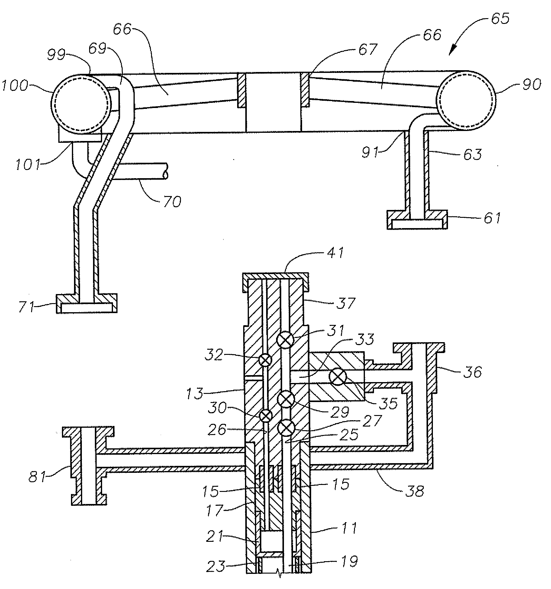
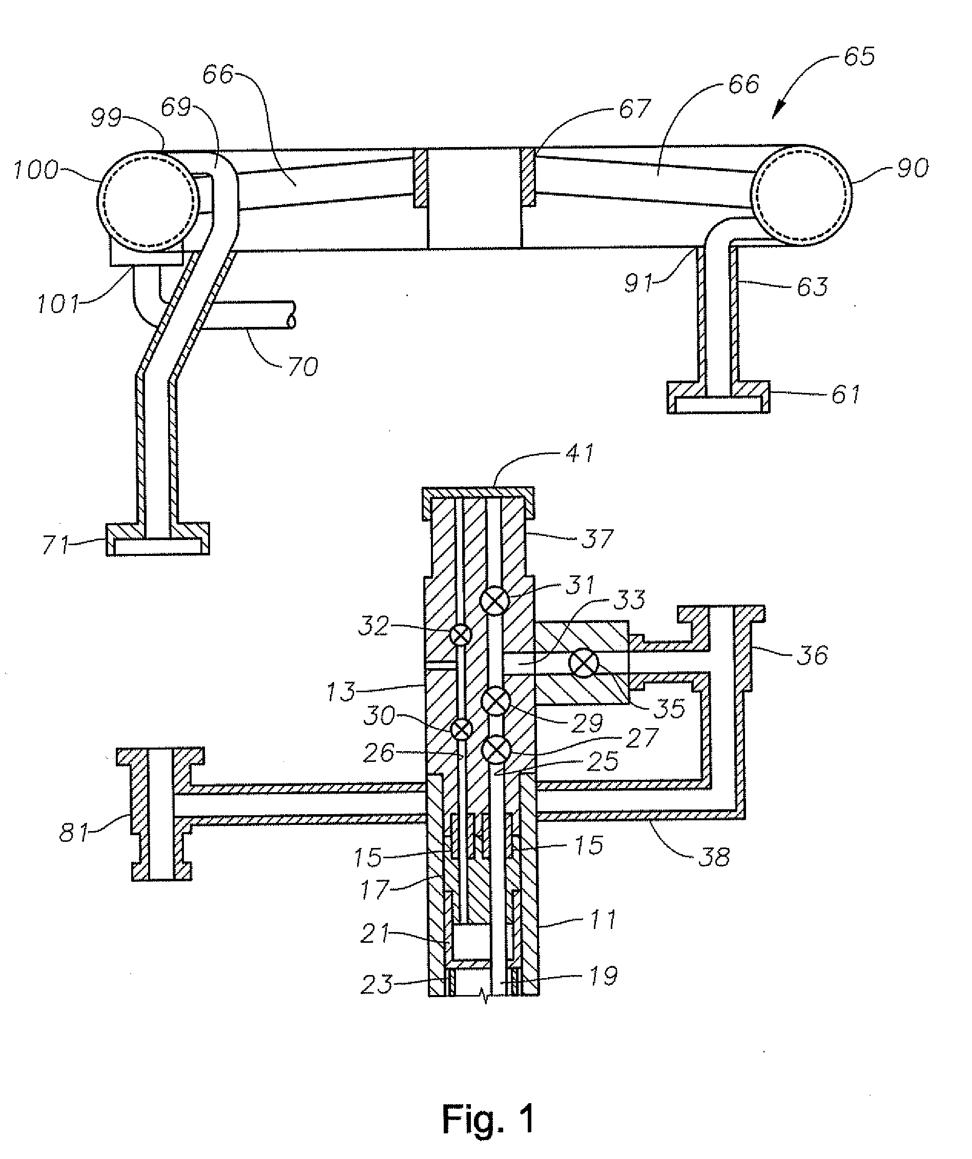
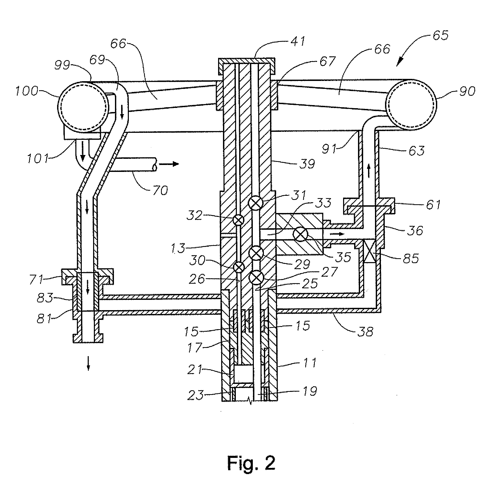
[0017]Referring to FIG. 1, a wellhead housing 11 is located at the upper end of a subsea well. Wellhead housing 11 is a large tubular member mounted to a conductor pipe that extends to a first depth in the well. A subsea Christmas or production tree 13 is secured to the upper end of wellhead housing 11 by a conventional connector. In this embodiment, tree 13 has isolation tubes 15 that extend downward into sealing engagement with the production and annulus bores of a tubing hanger 17. Tubing hanger 17 supports a string of production tubing 19 that extends into the well and is located sealingly in wellhead housing 11. At least one casing hanger 21 is supported in wellhead housing 11, each casing hanger 21 being secured to a string of casing 23 that extends into the well and is cemented in place.

[0018]Tree 13 has an axially extending production bore 25 that communicates with one isolation tube 15 and extends upward through the tree. An annulus bore 26 communicates with the other isola...


PUM

PropertyMeasurementUnit
weightaaaaaaaaaa
hydrostatic forcesaaaaaaaaaa
sizeaaaaaaaaaa

Abstract

A compact, low footprint water separation system for use in subsea well operations. A subsea production tree has a vertical passage and at least one laterally extending branch. A subsea gravity separation device having a hollow toroidal body detachably is mounted around and connected to the production tree. An inlet on a first side portion of the separation device is connected to the at least one laterally extending branch of the production tree and admits production fluid. The production fluid flows through the separation device where it passes through a separation unit. After passing through a separation unit, less dense fluid is discharged through an upper outlet and more dense fluid is discharged through a lower outlet. The upper and lower outlets are positioned opposite the first side portion of the separation device.

Description

CROSS-REFERENCE TO RELATED APPLICATION[0001]This application claims priority to provisional application 61 / 048,030, filed Apr. 25, 2008.FIELD OF THE INVENTION[0002]This disclosure relates to a water separator, and in particular, to a toroidal water separator for subsea well operations.BACKGROUND OF THE INVENTION[0003]Oil and gas wells typically produce a well fluid that requires separation to remove formation water from the flow stream. With subsea wells, the separation typically takes place on a production platform or vessel. This usually requires pumping the well fluid, including the formation water, to the surface production facility. In deep water installations, thousands of feet deep, the energy required to pump the water is extensive.[0004]Locating the separation unit subsea has been proposed and done on at least one occasion. The environment of a subsea separation unit and a surface unit differs because of the high hydrostatic forces imposed on the separation vessels. While v...

Claims


Application Information

Patent Timeline
Patent Type & Authority Applications(United States)
IPC IPC(8): E21B43/36
CPCE21B43/36
Inventor FENTON, STEPHEN P.
Owner VETCO GRAY
Why Eureka
Try Eureka