Clip and illuminate device

a technology of illumination device and clip, which is applied in the direction of lighting support device, lighting and heating apparatus, instruments, etc., can solve the problems of increasing the number of second clips with respect to the number of lamps, increasing and deteriorating the installation workability of clips, so as to improve the workability of lamps whose juxtaposition intervals differ, the number of kinds of clips can be reduced, and the cost of illuminant device can be reduced.

Inactive Publication Date: 2009-11-12
SHARP KK
View PDF11 Cites 18 Cited by
  • Summary
  • Abstract
  • Description
  • Claims
  • Application Information

AI Technical Summary

Benefits of technology

[0018]Another object is to provide a clip capable of clipping the lamps as a common clip, even in an illuminant device in which juxtaposition intervals of the lamps differ, by providing distance changing means capable of changing a distance between at least two of said clipping portions in a direction in which said lamps are juxtaposed.
[0085]Furthermore, according to the present invention, the lamps whose juxtaposition intervals differ can be clipped easily, without adjusting a distance between two clipping portions in the juxtaposition direction.

Problems solved by technology

However, in a case of the above (1), since two or more lamps cannot be clipped at once, there is a problem that the number of the second clips with respect to the number of the lamps increases, and the install workability of the clips deteriorates.
In a case of the above (2), there is a problem that a molding tool is required for each of a plurality of kinds of the first clips corresponding to juxtaposition intervals of the lamps, and a manufacturing cost of the clip including depreciation of the molding tool and accordingly, a cost of the illuminant device increase.
Since a plurality of kinds of clips are formed according to a model of the illuminant device as mentioned above, the molding tool is required for each kind of clip, and the manufacturing cost of the clip including depreciation of the molding tool and accordingly, the cost of the clip, and the cost of the illuminant device increase, and hence a remedy is required.

Method used


Image

  • Clip and illuminate device
  • Clip and illuminate device
  • Clip and illuminate device

Examples


Embodiment Construction

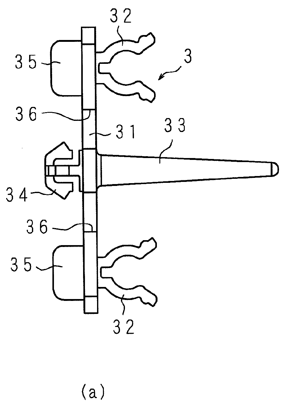
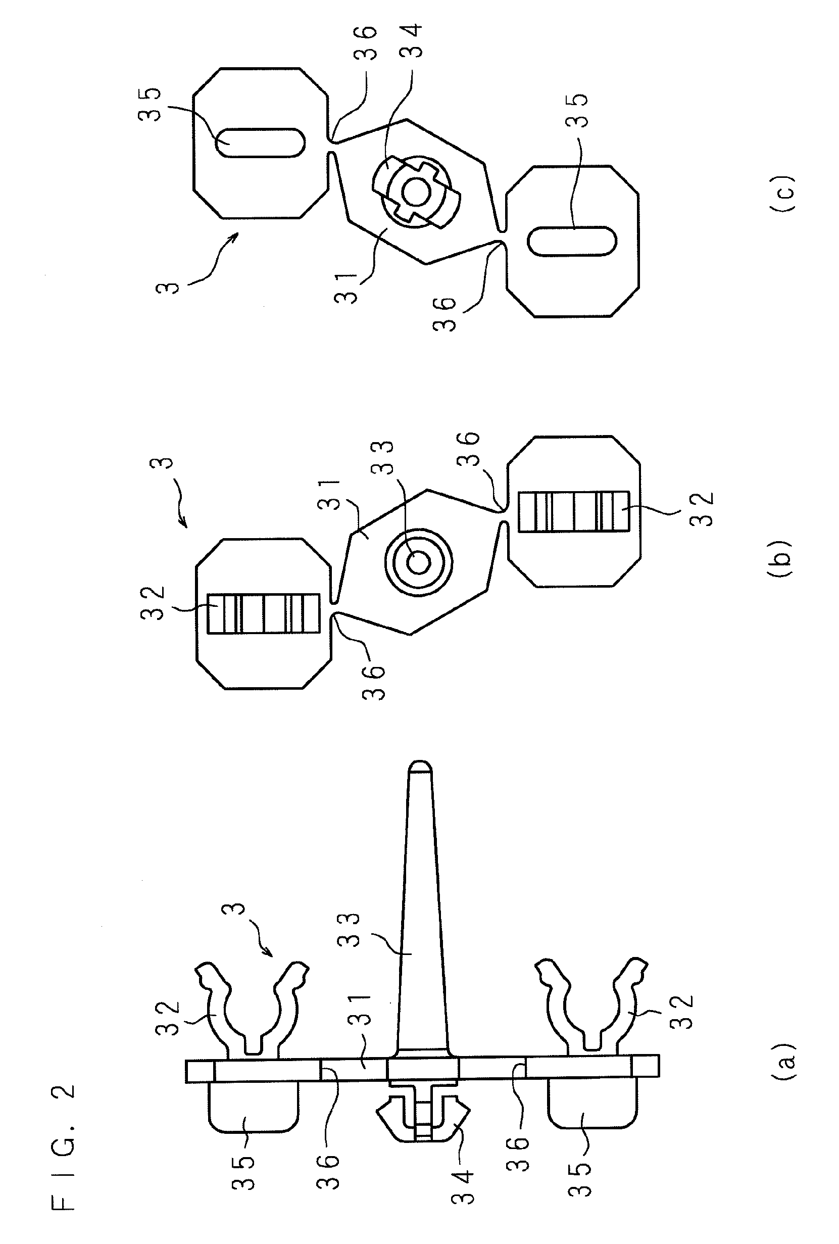
[0112]In the following, the present invention is detailed based upon drawings showing embodiments thereof. FIG. 1 shows a construction of a clip according to the present invention, in which (a) is a front view, (b) is a right side view, and (c) is a left side view. FIG. 2 shows a state where a distance between clipping portions is shortened, in which (a) is a front view, (b) is a right side view, and (c) is a left side view. FIG. 3 is an explanatory view showing a relationship between the clip and a supporting member, FIG. 4 is a front view showing a construction of an illuminant device provided with the supporting member which supports lamps whose juxtaposition intervals are large, FIG. 5. is a front view showing a construction of the illuminant device provided with the supporting member which supports lamps whose juxtaposition intervals are narrow, FIG. 6 is an expanded sectional view showing a state where the clip is mounted on the supporting member, and FIG. 7 is a front view sh...


PUM


Abstract

A plurality of clipping portions which clip a plurality of lamps to be juxtaposed are provided on one face, and a mounting portion to be mounted on a supporting member by which said lamps are supported, and holding projecting portions for holding positions of the clipping portions with respect to said supporting member are provided, and two flexible portions which can bend in a direction in which a distance between said supporting sections is changed are provided between at least two clipping portions.

Description

[0001]This application is the national phase under 35 U.S.C. §371 of PCT International Application No. PCT / JP2007 / 62672 which has an International filing date of Jun. 25, 2007 and designated the United States of America.BACKGROUND[0002]1. Technical Field[0003]The present invention relates to a clip which clips a rod-shaped lamp, and an illuminant device used as an illuminant of a display device such as a liquid crystal display.[0004]2. Description of Related Art[0005]In a display device such as television, the illuminant device is arranged on a back side of the display unit which has a display surface which displays an image on a front side thereof.[0006]The illuminant device comprises a supporting member (housing) which has a plurality of lock holes in a back wall and is open on a front side, a plurality of rod-shaped lamps which are juxtaposed up and down at equal intervals in said supporting member, a holder which holds both ends of said lamps on said back wall, and a plurality o...

Claims


Application Information

Patent Timeline
Patent Type & Authority Applications(United States)
IPC IPC(8): G02B6/00F21V21/088A44B21/00A44B99/00
CPCF21V19/008F21Y2103/00G02F1/133604Y10T24/44983G02F2201/465Y10T24/44017G02F1/133608
Inventor YOKOTA, MASASHIOKAZAKI, MASAKIFUKAI, HIROKITAKEUCHI, HIDETOSHIMIZU, MASAKI
Owner SHARP KK
Why Eureka
Try Eureka