
Thin-film capacitor and automatic production equipment and method thereof

A technology for film capacitors and production equipment, applied in the field of film capacitors and their automated production equipment, can solve the problems of low corner bending efficiency of film capacitor pins, cumbersome steps for pressing and aligning pins, affecting processing accuracy, and the like.

Inactive Publication Date: 2020-09-04
温州源利智能科技有限公司
View PDF9 Cites 8 Cited by
  • Summary
  • Abstract
  • Description
  • Claims
  • Application Information

AI Technical Summary

Problems solved by technology

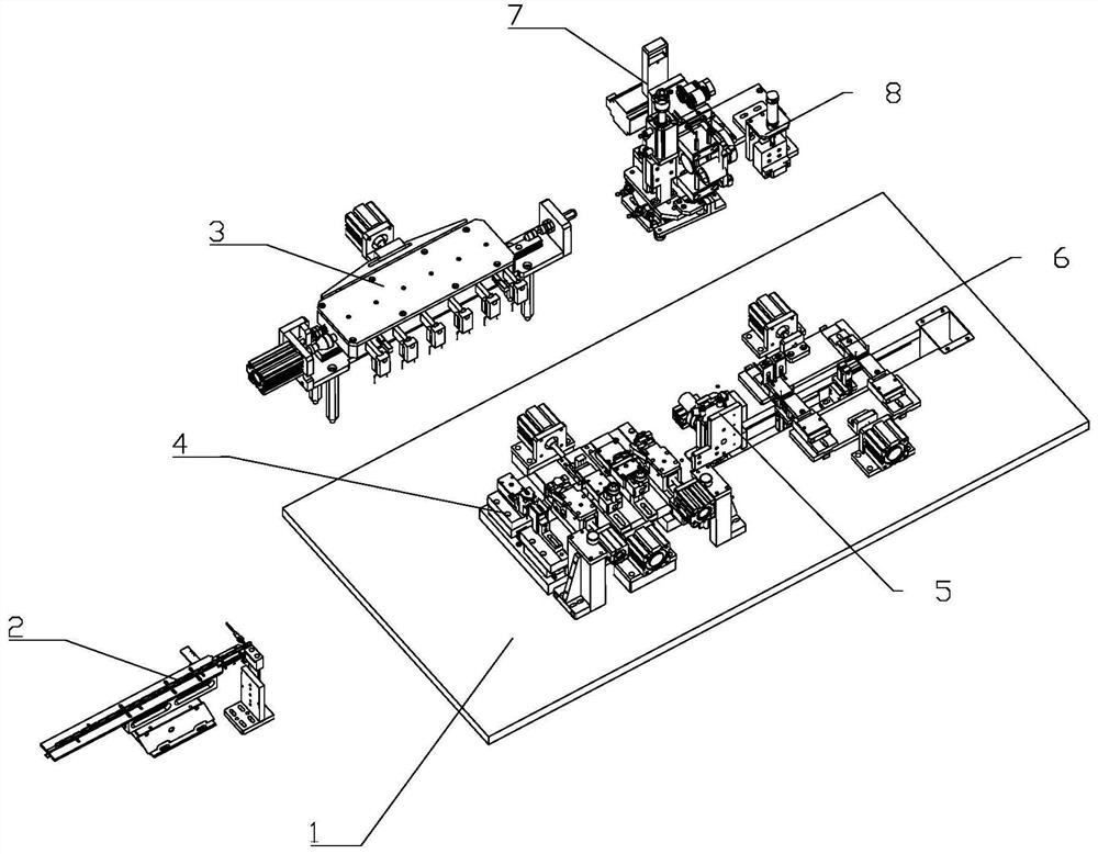
[0004] The purpose of the present invention is to: in the prior art, the multi-station moving efficiency of the film capacitor is low, the structure is complex, and it is easy to make mistakes; the uneven pins of the film capacitor affect the processing accuracy, the steps of pressing the pins are cumbersome, and the lengths of the pins of the film capacitor are different. , The bending efficiency of the corners on both sides of the film capacitor pins is low; it is difficult to install the heat shrinkable tube in the upright position of the film capacitor, and it is difficult to align the heat shrinkable tube; For the problem of alignment, a thin film capacitor with high moving efficiency and accurate position is proposed; the pins are flat and uniform in length, and the bending is completed twice, and the forming and bending efficiency is high; the mobile capacitor is inverted, and the capacitor pins are adjusted Positioning, easy to wear tube; heat-shrinkable tube assembly integration, film capacitor automatic production equipment with high success rate of tube insertion and its working method

Method used


Image

  • Thin-film capacitor and automatic production equipment and method thereof
  • Thin-film capacitor and automatic production equipment and method thereof
  • Thin-film capacitor and automatic production equipment and method thereof

Examples


Embodiment Construction

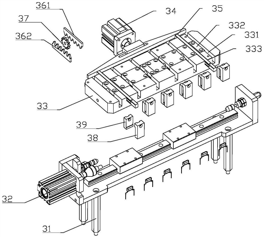
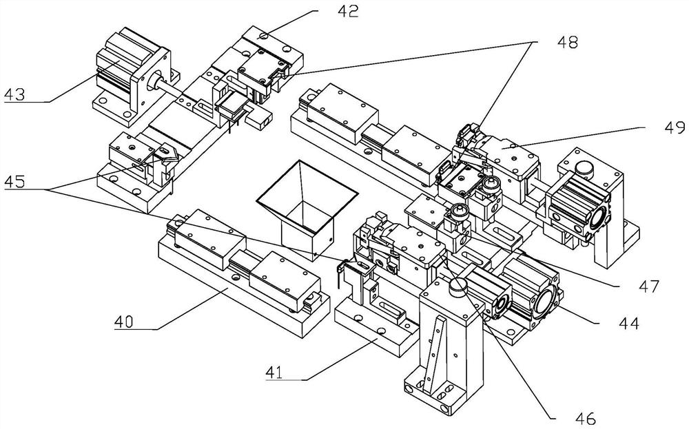
[0040] Such as figure 1 As shown, a film capacitor automatic production equipment includes a frame 1 and a feeding and conveying device 2 installed on the frame 1, a clamping and transferring device 3, a multifunctional forming device 4, a rotating material turning device 5, and a flip-chip conveying device. Device 6, pipe threading device 7 and pipe pressing device 8; feeding and conveying device 2 is connected with clamping and transporting device 3, and multi-functional forming device 4 is located below clamping and transporting device 3; described rotating material turning device 5 The multifunctional molding device 4 is connected with the flip-chip conveying device 6; the pipe threading device 7 and the tube pressing device 8 are located above the flip-chip conveying device 6, and the frame 1 is also provided with a blanking barrel, and the falling The material barrel is connected with the discharge side of the inverted conveying device 6, and the frame 1 is also provided...


PUM


Abstract

The invention relates to the technical field of capacitor production. Automatic production equipment of a thin-film capacitor comprises a rack, and a feeding conveying device, a clamping and transferring device, a multifunctional forming device, a rotary material overturning device, an inverted conveying device, a pipe penetrating device and a pipe pressing device which are mounted on the rack, the feeding conveying device is connected with the clamping and transferring device, and the multifunctional forming device is located under the clamping and transferring device. The multifunctional forming device is connected with the inverted conveying device through the rotary material overturning device. The pipe penetrating device and the pipe pressing device are located over the inverted conveying device, the rack is further provided with a discharging barrel, and the discharging barrel is connected with the discharging side of the inverted conveying device. According to the invention, movement between film capacitor stations is efficient and positional accurate, the pins are flat and uniform in length, twice bending is completed by one action, and the forming and bending efficiency ishigh; the mobile capacitor is inverted to position a capacitor pin, so that pipe penetration is facilitated; and the heat shrink tube is integrally assembled, and the success rate of pipe penetrationis high.

Description

technical field [0001] The invention relates to the technical field of capacitor production, in particular to a film capacitor and its automatic production equipment and method. Background technique [0002] Film capacitors use metal foil as an electrode, and it is laminated with plastic films such as polyethylene, polypropylene, polystyrene or polycarbonate from both ends, and then wound into a cylindrical capacitor. According to the type of plastic film, it is called polyethylene capacitor (also called Mylar capacitor), polypropylene capacitor (also called PP capacitor), polystyrene capacitor (also called PS capacitor) and polycarbonate capacitor. Film capacitors are excellent capacitors due to their many excellent characteristics. Its main characteristics are as follows: non-polarity, high insulation resistance, excellent frequency characteristics (broad frequency response), and low dielectric loss. Based on the above advantages, film capacitors are widely used in analo...

Claims


Application Information

Patent Timeline
IPC IPC(8): H01G4/228H01G4/33H01G13/00
CPCH01G4/228H01G4/33H01G13/00H01G13/006
Inventor 王伟波万广科万国花
Owner 温州源利智能科技有限公司
Learn More