
Bird feeding port assembly

a technology for feeding ports and feeders, applied in the field of feeders, can solve the problems of conventional bird feeding port assemblies, waste of resources, and additional costs, and achieve the effect of feeders, and reducing the number of feeders

Inactive Publication Date: 2009-11-19
CRANSWICK PET & AQUATICS
View PDF18 Cites 30 Cited by
  • Summary
  • Abstract
  • Description
  • Claims
  • Application Information

AI Technical Summary

Benefits of technology

[0007]It is an object of the present invention to provide a bird feeding port assembly which provides a perch which can be stowed away for storage and for transportation.
[0008]It is another object of the present invention to provide a bird feeding port assembly which can be closed to prevent bird feed escaping from the bird feeder. According to the present invention there is provided a bird feeding port assembly for mounting to a bird feed containment housing through an opening in the wall of the housing, the assembly defining a feeding area having an opening to the housing, a support frame which is adapted in use to secure the assembly to the housing such that the opening to the housing allows seed to follow into the feed area, and a closure member which is moveably between a first extended position in which the closure member extends outwardly from the outward side of the assembly leaving the feeding area open and a second retracted position in which the closure member overlies the feeding bowl and prevents access thereto.
[0009]When the assembly according to the present invention is mounted to a bird feed containment housing bird feed passes from the housing through the opening in the wall thereof and into the feeding area. When the bird feeder is being transported the closure member is closed to overlie the feeding area and thereby prevent bird feed from leaking out. When the bird feeder is positioned for use the closure member is pulled out into the extended position, thereby opening the feeding area and allowing birds access to the bird feed contained therein. In the extended position the closure member serves as a perch on which birds can stand to feed from the feeding area.
[0010]In a preferred embodiment of the present invention the feeding bowl comprises a feeding bowl having an opening in the rear thereof and the support means is adapted to secure the feeding bowl to the exterior of the housing such that the opening in the rear of the feeding bowl is aligned with the opening in the housing wall. The assembly further comprises a cover or hood located above and spaced from the feeding bowl. The space between the cover and the feeding bowl is sufficient to allow birds access to the interior of the feeding bowl, whilst preventing rain from falling into the bowl and spoiling the bird feed held therein. The feeding bowl and the cover may be formed together as a single unitary construction, by, for example, moulding them in plastics material.
[0012]Preferably the closure member comprises a stop bar on the rearward edge thereof which prevents it from being slide out of the slots and / or grooves in the feeding bowl which retain it. In one embodiment the stop bar abuts against the inner face of the outward side of the feeding bowl. In another embodiment of the present invention the closure member extends through the opening in the rear of the feeding bowl and into the housing, and the stop bar engages against the uppermost side of the opening. In this embodiment the rearward edge of the closure member is shaped so as to substantially match the shape of the feeding bowl. This ensures that when the closure member is in the first extended position the rearward edge of the closure member lies over or past the feeding bowl, thereby facilitating full access to the contents of the feeding bowl.

Problems solved by technology

This incurs additional costs and is wasteful of resources.
Conventional bird feeding port assemblies, such as that disclosed in UK Patent No. 2398719, are not suitable for use with bird feeders which are pre-filled with bird feed.
There is no mechanism for closing the port in the assembly and as a result bird feed leaks out during movement of the bird feeder.

Method used


Image

  • Bird feeding port assembly
  • Bird feeding port assembly
  • Bird feeding port assembly

Examples


Embodiment Construction

)

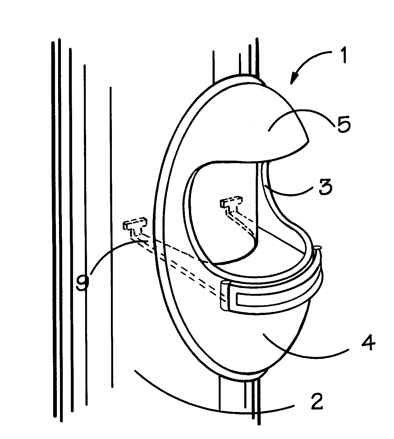
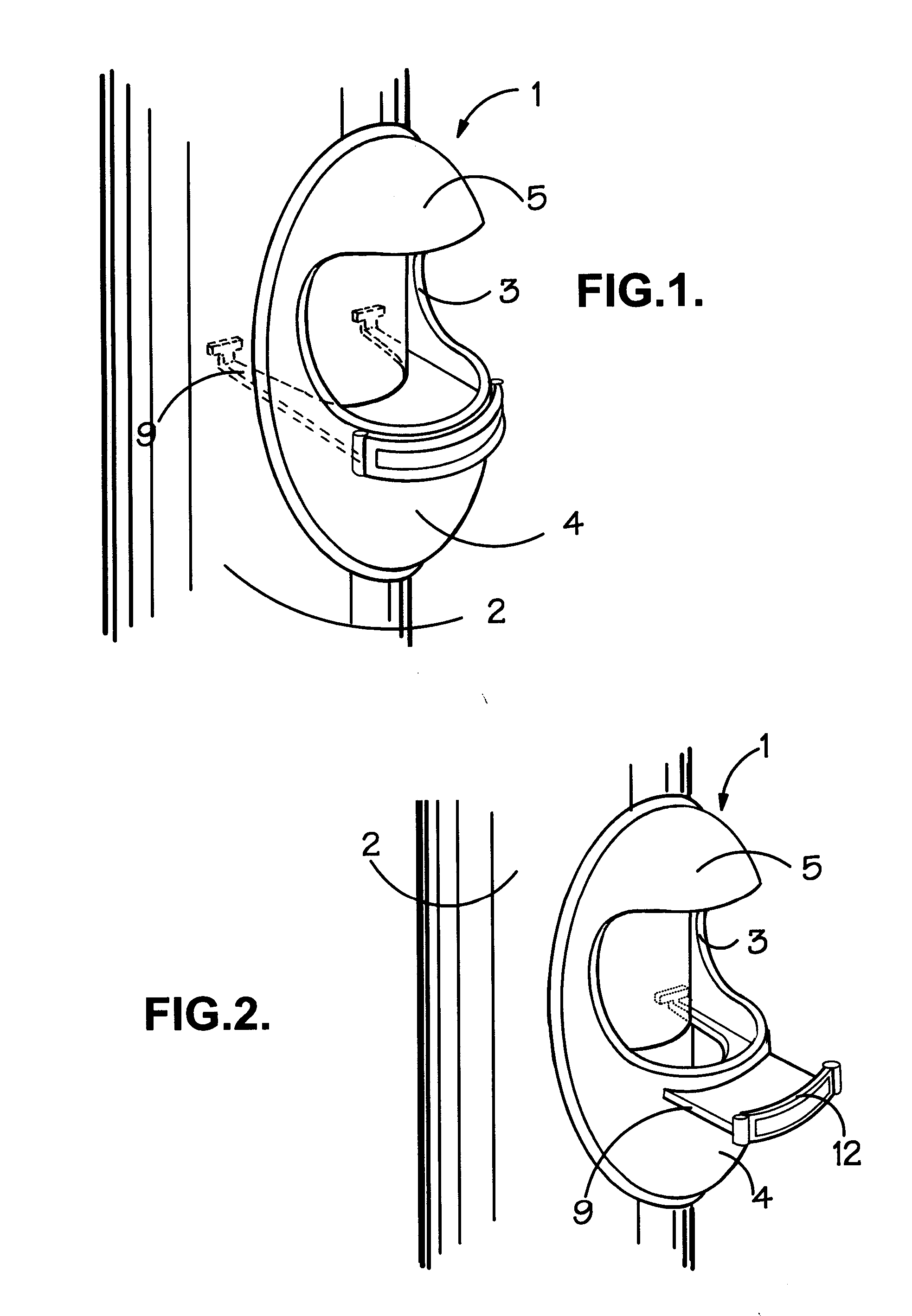
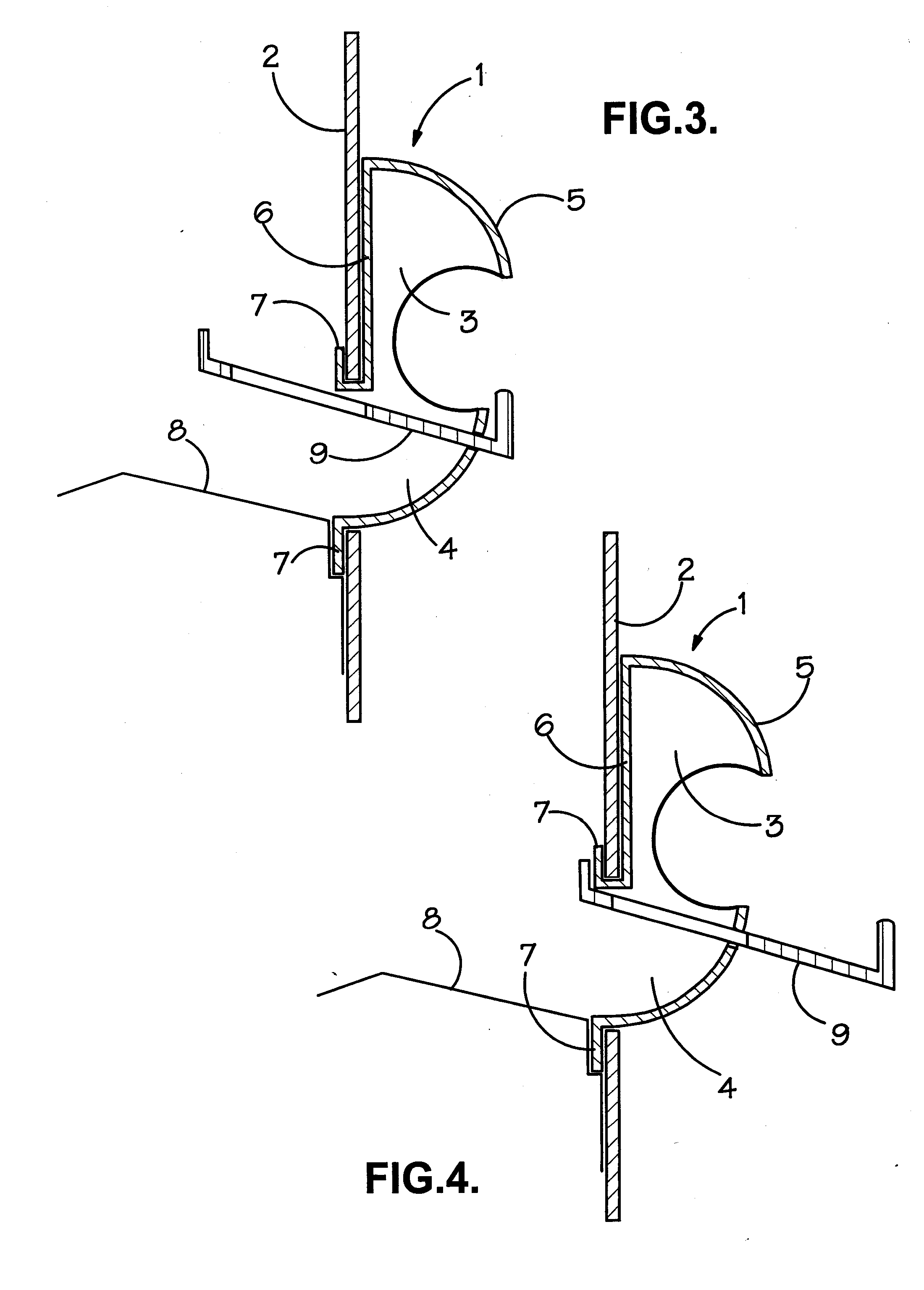
[0022]Referring to the accompanying drawings there is shown a bird feeding port assembly according to the present invention, generally designated by the reference 1, which is mounted to a bird feed containment housing 2 through an opening (not visible) in the wall thereof. In FIGS. 1, 3 and 5 the assembly 1 is shown in a fully closed position. In FIGS. 2, 4 and 6 the assembly 1 is shown in a fully open position. The assembly 1 comprises a first part 3 which defines a feeding bowl 4 and a cover 5 for the feeding bowl 4. The cover 5 is spaced from the feeding bowl 4 to defining an opening through which a bird may access bird feed contained within the feeding bowl 4, whilst still shielding the feeding bowl against rainfall which might otherwise spoil the bird feed. Referring to FIG. 3 of the drawings it can be seen that the first part 3 further comprises a back wall 6 which is so shaped as to sit flush to the outer wall of the housing 2 and which defines an aperture immediately behind...


PUM


Abstract

A bird feeding port assembly (1) for mounting to a bird feed containment housing (2) through an opening in the wall of the housing (2), the assembly (1) defining a feeding area (4) having an opening to the housing (2), a support frame (3) which is adapted in use to secure the assembly (1) to the housing (2) such that the opening to the housing allows seed to flow into the feed area (4), and a closure member (9) which is moveable between a first extended position in which the closure member (9) extends outwardly from the outward side of the assembly (1) leaving the feeding area (4) open and a second retracted position in which the closure member (9) overlies the feeding area (4) and prevents access thereto.The feeding area (4) may comprise a bowl (4) that can project outwardly from, or be located within, the containment housing (2). The closure member (9) can pivot or slide between the first and second positions.

Description

BACKGROUND OF THE INVENTION[0001]1. Field of the Invention[0002]The present invention relates to bird feeders. More specifically, the present invention relates to a bird feeding port assembly for mounting to a bird feed containment housing through feed openings in the wall of the housing.[0003]2. Background Art[0004]Commercially available bird feeders come in a great variety of designs and configurations. One such bird feeder comprises a vertically orientated housing for retaining the bird feed with one or more openings in the wall of the housing to facilitate access to bird feed within the housing. A bird feeding port assembly is mounted in each opening, and generally comprises a locating member which serves to locate the assembly in the opening and which defines a port into the interior of the housing, a perch which extends outwardly from the assembly at the bottom of the port, and a deflector which extends rearwardly of the locating member into the housing exterior to cover or sh...

Claims


Application Information

Patent Timeline
Patent Type & Authority Applications(United States)
IPC IPC(8): A01K39/012
CPCA01K39/012
Inventor BLACK, DEREK JAMES
Owner CRANSWICK PET & AQUATICS
Learn More