
Cursor motion blurring

a cursor and motion blurring technology, applied in the field of cursor motion blurring, can solve the problems of difficult, difficult, and difficult to determine the current position of the cursor displayed on the large screen designed to be placed at a distance from the user

Inactive Publication Date: 2009-11-19
APPLE INC
View PDF17 Cites 90 Cited by
  • Summary
  • Abstract
  • Description
  • Claims
  • Application Information

AI Technical Summary

Benefits of technology

The patent describes a method for displaying the movement of a cursor on a screen using a remote controller. The electronic device can define a trail that follows the movement of the cursor and can adjust its size, color, or opacity based on the speed of the cursor. This makes it easier for the user to track the cursor on screen and can make the trail transparent or opaque depending on the speed of the cursor. The technical effect of this patent is to provide a more intuitive and user-friendly experience for controlling the movement of the cursor on a screen.

Problems solved by technology

Although current displays often have high enough refresh rates that cursor trails are not required, determining the current position of cursors displayed on large screens designed to be placed at a distance from the user (e.g., cursors displayed on a television screen located across a room from the user) may be difficult.
For example, the cursor may be so small that it is not easily seen from a distance, while making the cursor larger may take up such a large portion of the display that it becomes difficult, or perhaps unfeasible to select options displayed options (e.g., the cursor is larger than adjacent displayed options).

Method used


Image

  • Cursor motion blurring
  • Cursor motion blurring
  • Cursor motion blurring

Examples


Embodiment Construction

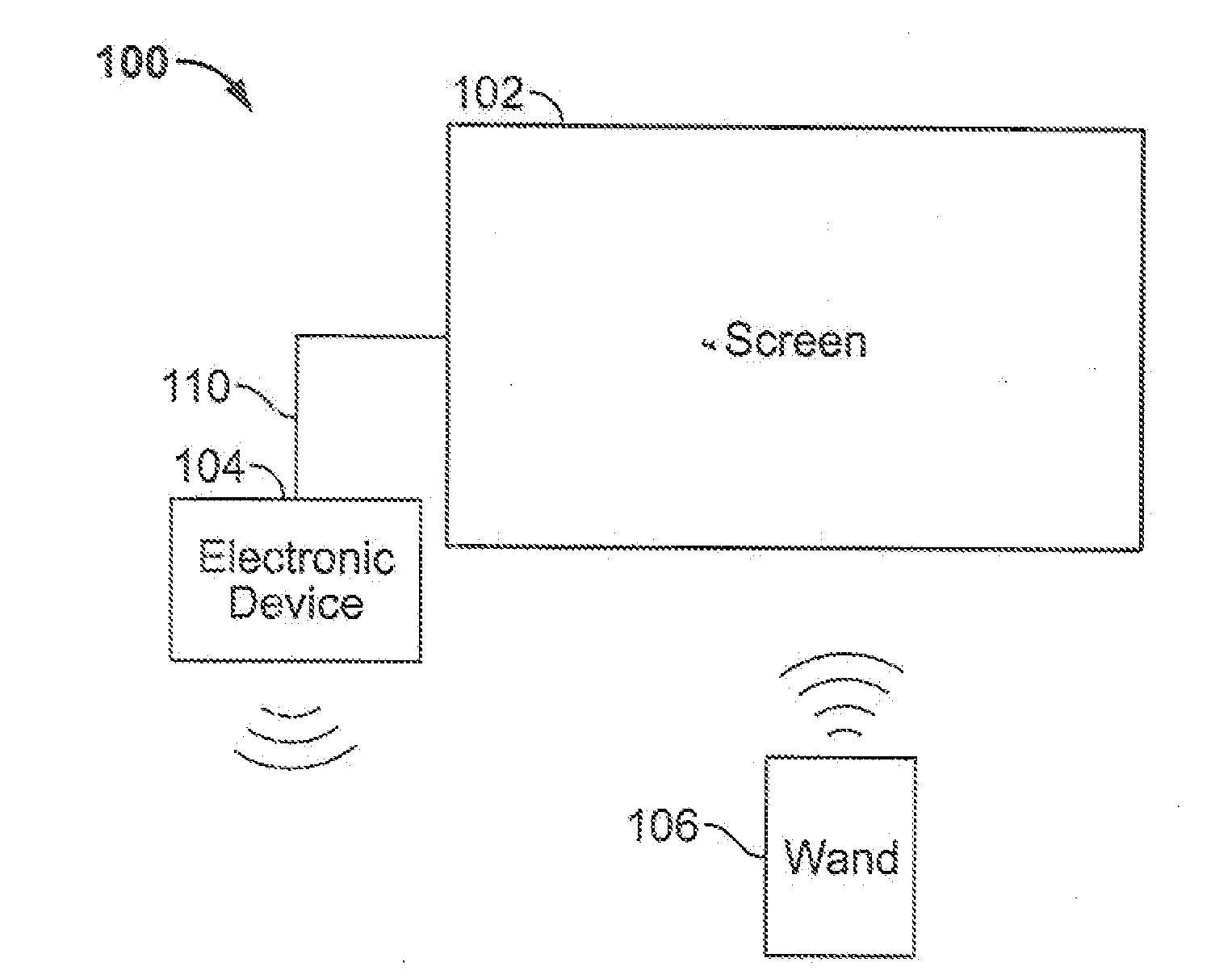
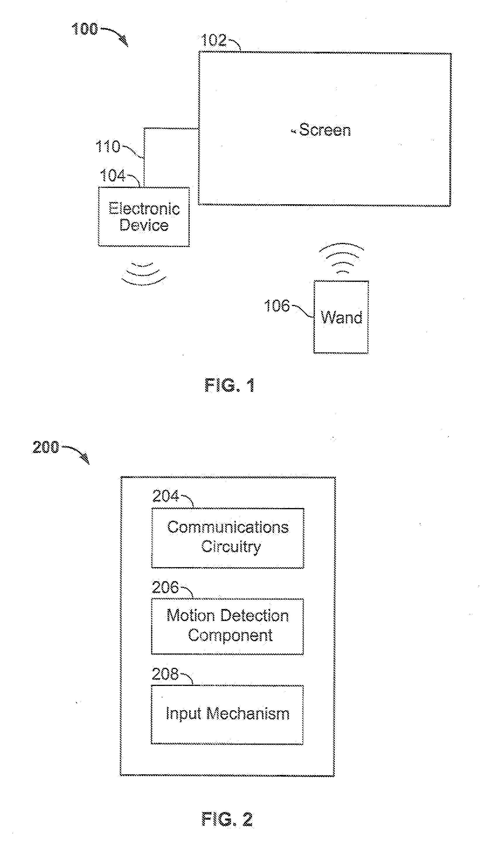
[0019]FIG. 1 is a schematic view of an illustrative media system in which a cursor may be displayed in accordance with one embodiment of the invention. In the example of FIG. 1, the display of the cursor is controlled based on the orientation of a remote wand. Other illustrative media systems used with wands are described in commonly owned U.S. patent application Ser. No. 12 / 113,588, filed May 1, 2007, and commonly owned U.S. patent application Ser. No. 12 / 002,063, filed Dec. 14, 2007, both of which are incorporated herein in their entirety. It will be understood, however, that the position of the cursor may be controlled using any suitable approach, including for example using a keyboard, directional keys, mouse, touch pad, touch screen, scroll wheel, or any other suitable input mechanism.

[0020]As shown in FIG. 1, media system 100 may include screen 102, electronic device 104 and wand 106. Screen 102 may be any suitable screen or display for displaying media or other content to a u...


PUM


Abstract

An electronic device for displaying a cursor with a trail is provided. The user may control electronic device operations by navigating the cursor on a display. To assist the user in identifying the current location of the cursor, the electronic device may define and display a trail indicating the prior positions of the cursor. For example, the electronic device may identify previous cursor positions and draw a curve, for example a spline, connecting the previous cursor positions and the current cursor position. The curve may have a varying width, thus forming a trail for which the wider portion is adjacent the cursor, and for which the narrower portion is adjacent the tip of the curve. The electronic device may instead or in addition modify the opacity of the curve, for example based on the instantaneous speed of the cursor. In some embodiments, other trail characteristics (e.g., size, color, opacity, path) may be modified based on prior cursor movements or cursor speed.

Description

BACKGROUND OF THE INVENTION[0001]This invention is related to depicting the movement of a cursor displayed on a screen by a media system in response to inputs from a remote controller.[0002]Electronic devices may be controlled by a user using many different approaches. In some embodiments, a cursor that may be controlled by the user is displayed on a screen of or coupled with the electronic device. Using an input mechanism such as a remote controller, the user may navigate the cursor on the screen over selectable options and provide a selection input. The electronic device may then perform any suitable action associated with the selected option.[0003]To assist the user in tracking the location of the cursor, some electronic devices may show prior cursor locations as the cursor moves along the screen. For example, some computer operating systems may include an option for creating a trail behind the cursor. The operating system may continue to display a cursor in a position from which...

Claims


Application Information

Patent Timeline
Patent Type & Authority Applications(United States)
IPC IPC(8): G06T11/20
CPCG06F3/0481G06T13/80G06F2203/04801
Inventor KERR, DUNCAN R.KING, NICHOLAS V.
Owner APPLE INC
Learn More